
 Business
> Industrial Devices
> Automation Controls Top
> FA Sensors & Components
> Sensors
> Photoelectric Sensors / Laser Sensors
> Robust Photoelectric Sensor RX(Discontinued Products)
> I/O Circuit and Wiring diagrams
Business
> Industrial Devices
> Automation Controls Top
> FA Sensors & Components
> Sensors
> Photoelectric Sensors / Laser Sensors
> Robust Photoelectric Sensor RX(Discontinued Products)
> I/O Circuit and Wiring diagrams
Robust Photoelectric Sensor RX (Discontinued Products)
|
We are sorry, the products have been discontinued. Please refer to the details of the discontinued products and the recommended substitutes list below.
|
|
I/O Circuit and Wiring diagrams
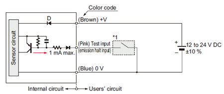
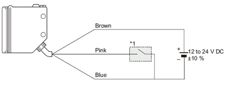
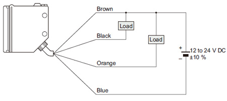
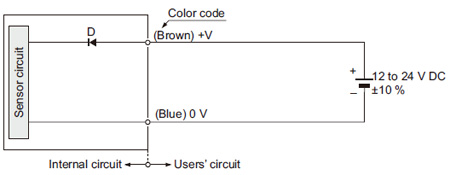
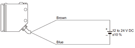
RX-□
RX4-□
|
|
|
|
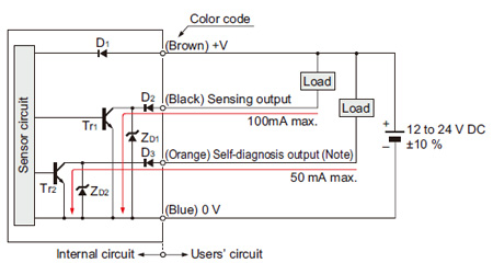
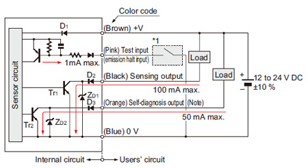
| Symbols・・・ | D1:Reverse supply polarity protection diode D2,D3:Reverse output polarity protection diode ZD1,ZD2:Surge absorption zener diode Tr1,Tr2:NPN output transistor |
|---|
|
|
| Symbols・・・ | D1:Reverse supply polarity protection diode D2,D3:Reverse output polarity protection diode ZD1,ZD2:Surge absorption zener diode Tr1,Tr2:NPN output transistor |
|---|
|
|
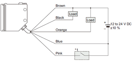
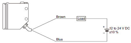
RX2-□
|
|
|
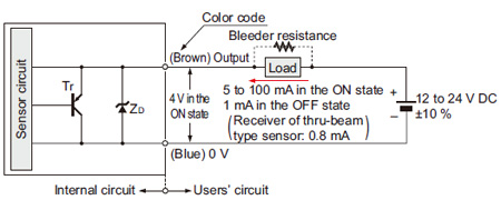
Conditions for the load
| 1) | The load should not be actuated by the leakage current (1 mA; 0.8 mA for receiver of thru-beam type sensor) in the OFF state. |
|---|---|
| 2) | The load should be actuated by (supply voltage – 4 V) in the ON state. |
| 3) | The current in the ON state should be between 5 to 100 mA DC. [In case the current is less than 5 mA, connect a bleeder resistance in parallel to the load (shown in dotted line above) so that a current of 5 mA, or more, flows.] |
|
BY EMAIL


Requests to customers (Automation Control Components & Industrial Device) [Excluding specific product]
Requests to customers (Automation Control Components & Industrial Device) [For specific product]
Requests to customers (FA Sensors & Components [Excluding motors])
Requests to customers (Dedicated to industrial motors)
- COMPONENTS & DEVICES
- FA SENSORS & COMPONENTS
- Fiber Sensors
- Photoelectric Sensors / Laser Sensors
- Micro Photoelectric Sensors
- Light Curtains / Safety Components
- Area Sensors
- Inductive Proximity Sensors
- Particular Use Sensors
- Sensor Options
- Wire-Saving Systems
- Programmable Controllers / Interface Terminal
- Human Machine Interface
- Pressure Sensors / Flow Sensors
- Measurement Sensors
- Static Control Devices
- Laser Markers / 2D Code Readers
- Machine Vision System
- Energy Management Solutions
- Timers / Counters / FA Components
- MOTORS
![]()