
 Business
> Industrial Devices
> Automation Controls Top
> Components & Devices
> Relays / Couplers
> Automotive Relays
> Definition of Automotive Relay Terminology
Business
> Industrial Devices
> Automation Controls Top
> Components & Devices
> Relays / Couplers
> Automotive Relays
> Definition of Automotive Relay Terminology
Definition of Automotive Relay Terminology
- From a safety perspective, the use of the automotive relay requires manufacturers of automobiles and automotive equipment to confirm specifications and conduct evaluation tests. Therefore, these products are for sale to automotive manufacturers and automotive component manufactures only.
- Please inquire with manufacturers of automobiles and automotive equipment about the specifications of automotive relay mounted in vehicle bodies and equipment.
- Please understand that safety considerations prevent us from receiving inquiries from or dealing with private customers.
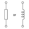
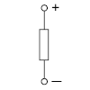
1. Coil (Also Referred to as Primary or Input)
1.Coil Designation
| Single side stable type | |
|---|---|
| Non-polarized | Polarized |
 |
 |
2.Rated Coil Voltage
The voltage applied to the operating coil during normal use of the relay. The expected life and other guaranteed values are based on the rated coil voltage.
3.Rated Operating Current
The value of current flow in the coil when rated voltage is applied on the coil
4.Rated Operating Power
The value of power used by the coil at rated voltage.
(Rated Operating Power = Rated Coil Voltage × Rated Operating Current.)
5.Coil Resistance
This is the DC resistance of the coil in DC type relays for the temperature conditions listed in the catalog. (Note that for certain types of relays, the DC resistance may be for temperatures other than the standard 20°C 68°F.)
6.Operate (Set) Voltage
As the voltage on an unoperated relay is increased, the value which all contacts must function.
7.Release (Reset) Voltage
As the voltage on an operated relay is decreased, the value which all contacts must revert to their unoperated position. In the catalog, operate voltage and release voltage values are usually indicated for when the temperature condition is 20°C 68°F, however, for some relays, the values are indicated for when the temperature condition is 25°C 77°F.
8.Maximum Applied Voltage
The maximum voltage within the allowable range that can be applied to the operating coil. Continuous operation at this maximum value, however, is not allowable. Since the value depends on the ambient temperature, for each type, please check the value listed in the catalog.
2. Contacts (secondary or output)
1.Contact Arrangement
Denotes the contact mechanism and number of contacts in the contact circuit.
2.Contact Symbols
| Form A contacts (normally open contacts) |
Form B contacts (normally closed contacts) |
Form C contacts (changeover contacts) |
|---|---|---|
 |
 |
 |
Form A contacts are also called N.O. contacts or make contacts.
Form B contacts are also called N.C. contacts or break contacts.
Form C contacts are also called transfer contacts.
3.Rated Switching Capacity
Derived from the contact voltage and contact current, this is the reference value that determines the performance of the switching section.
4.Maximum Carrying Current
The maximum value for carrying current through the contact section. It is necessary to pay attention to carrying conditions during use.
5.Continuous Carrying Current
The current that, when the contact is closed, without raising beyond the specified limits the temperature of the relay contact and all other parts, can continuously carrying the contact section.
6.Contact Resistance
This value is the combined resistance of the resistance when the contacts are touching each other, the resistance of the terminals and contact spring. The contact resistance is measured using the voltage-drop method as shown below. The measuring currents are designated.
|
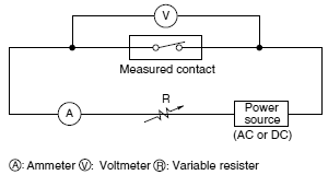
Test Currents
| Rated Contact Current or Switching Current (A) |
Test Current (mA) |
|---|---|
| 1 or more | 1,000 |
In general, for relays with a contact rating of 1A or more, measure using the voltage-drop method at 1A 6V DC.
3. Electrical Performance
1.Insulation Resistance
The resistance value between all mutually isolated conducting sections of the relay, i.e. between coil and contacts, across open contacts and between coil or contacts to any core or frame at ground potential. This value is for the relay alone, and does not take into consideration the solder land on the PC board or other factors.
- 1.Between contact and coil: between all contact terminals and coil terminals
- 2.Between open contacts: between open contact terminals
- 3.Between contact sets: between contact sets terminals
2.Dielectric Strength
When a high voltage is applied for 1 minute at the same points where insulated resistance is measured, the limit value for non-occurrence of dielectric breakdown. Leakage current is usually set at 10 mA. In special cases, however, it may be set at 1 mA or 3 mA.
3.Operate (Set) Time
The elapsed time from the initial application of power to the coil, until the closure of the Form A (normally open) contacts. This time does not include any bounce time.
|

4.Release (Reset) Time
The elapsed time from the initial removal of coil power until the reclosure of the Form B (normally closed) contacts. This time does not include any bounce time. Or, for relays with only Form A contact (1 Form A, 2 Form A), the time taken until the contact opens.
5.Contact Bounce (Time)
Generally expressed in time (ms), this refers to the intermittent switching phenomenon of the contacts which occurs due to the collision between the movable metal parts or contacts, when the relay is operated or released.
4. Mechanical Performance and Life
1.Shock Resistance
Shock resistance is categorized as either functional shock or destructive shock, which are defined below.
1) Functional
The shock which can be tolerated by the relay during operation, without causing the closed contacts to open for more than the specified time. The contact opening time itself is specified as 10 μs or less.
2) Destructive
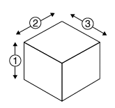
The shock which can be withstood by the relay during shipping, installation or use without it suffering damage, and without causing a change in its operating characteristics.
Testing is carried out with shock forces applied along each of the three axial directions.
|
2.Vibration Resistance
Vibration resistance is categorized as either functional vibration or destructive vibration, which are defined below.
1) Functional
The vibration which can be tolerated by the relay during service, without causing the closed contacts to open for more than the specified time. Here, the contact opening time value, is the same as for functional shock.
2) Destructive
The vibration which can be withstood by the relay during shipping, installation or use without it suffering damage, and without causing a change in its operating characteristics. Expressed as an acceleration in G’s or displacement, and frequency range. However, test was performed a total of six hours, two hours each in three-axis directions.
|
3.Mechanical Life
The number of times the relay can be operated under nominal conditions with no load on the contacts.
4.Electrical Life
The number of times the relay can be operated under nominal conditions with a specific load being switched by the contacts.
5.Maximum Switching Frequency
This refers to the maximum switching frequency which satisfies the mechanical life or electrical life under repeated operations by applying a pulse train at the rated voltage to the operating coil.
Notes:
- 1.Except where otherwise specified, the tests above are conducted under JIS standard temperature and humidity (15°C to 35°C 59°F to 95°F, 25 to 85%).
- 2.The coil applied voltage in the switching tests is a rectangular wave at the rated voltage.
Catalog Download
|
|
Title | Language | File size | Update |
|---|---|---|---|---|
| 用語説明 車載用リレー |
JP | 191.6KB | April 1, 2022 | |
| Definition of Relay Terminology Automotive Relays |
EN | 52.5KB | April 1, 2022 | |
| 用语说明 车载继电器 |
CN-Simplified | 672.9KB | August 20, 2013 |
BY EMAIL
- U.S.A.
- +1-800-344-2112
- Europe
- +49-89-45354-1000
- China
- +86-10-59255988
- Singapore
- +65-6299-9181


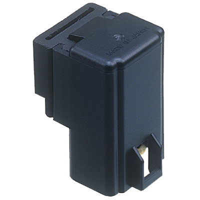
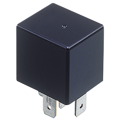
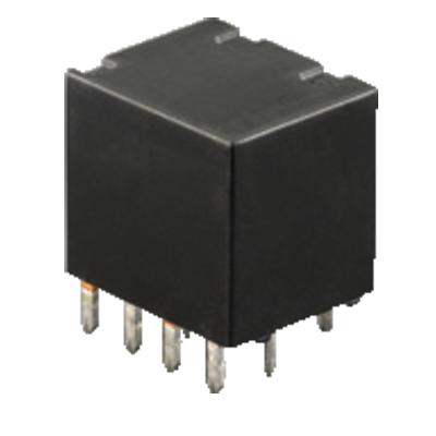
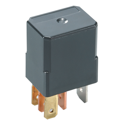
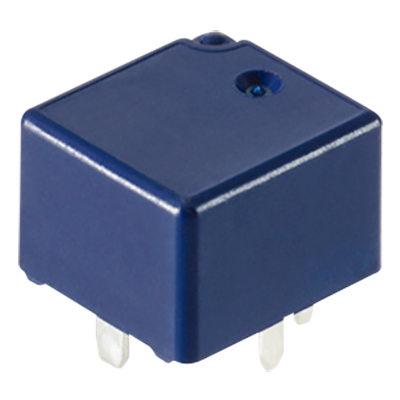
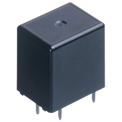
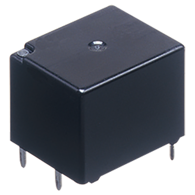
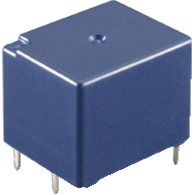
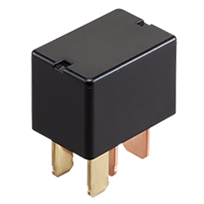
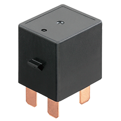
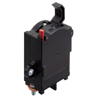
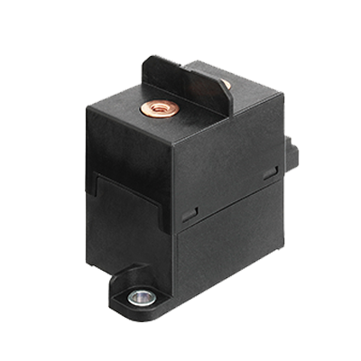
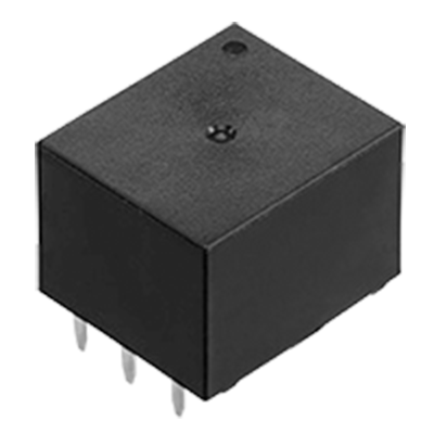
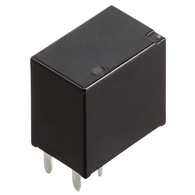
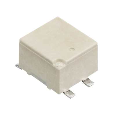
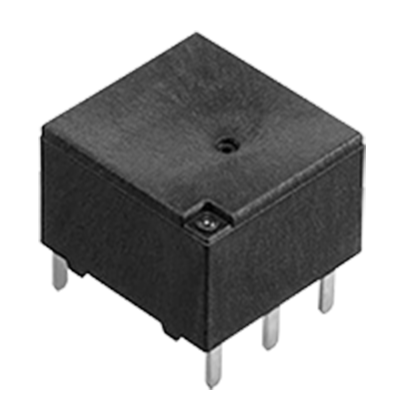
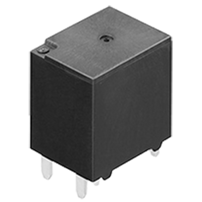
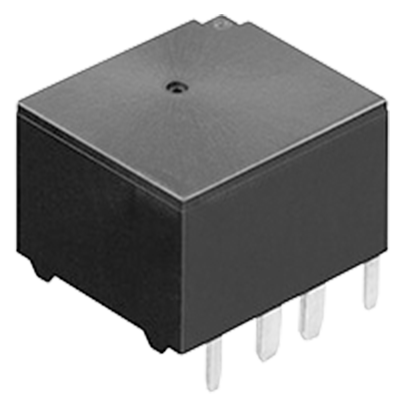
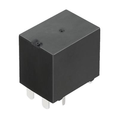
Automotive Relays
-
CA Relays Small Size, Light Weight Automotive Power Relays -
CB Relays Mini-ISO Automotive Relay -
CJ Relays Compact Slim Twin and Single Type Automotive Relay -
CM Relays Micro-ISO Automotive Relay -
CN-H Relays High Load Relay for Smart J/B -
CN-L Relays Max. 150 A Continuous Carrying Current Latching Relay -
CN-M Relays Middle Load Relay for Smart J/B -
CP Relays Compact Flat Size Relay for Automotive -
CP Relays Power type High Carrying Current Type, Miniature Low Profile Automotive Relay -
CQ Relays 1 Form C Automotive Quiet Relay -
CT Relays Small & Slim Twin/1 Form C type Automotive Relay -
CT Relays Power type High Carrying Current Type, Small & Slim Automotive Relay -
CV-N Relays Low profile Micro-ISO Automotive Relay -
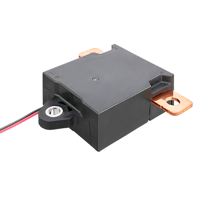
EB-N Relays Low height 100A 48V DC relay -
EC-N Relays Small, High Capacity, High Voltage DC Plug in Type Relay -
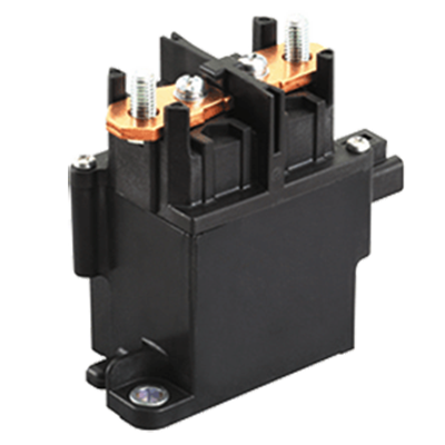
EV Relays (DC Contactors) High voltage DC, High capacity Cut-off Relays using Capsule Contact Mechanism -
EV Switches Capsule Contact High Voltage Cut-off Switch -
EV-A Relays (DC Contactors) High voltage & High Capacity Relays realized 500 V DC cut off -
TA Relays 1 Form C Automotive Quiet Relay -
TB Relays Miniature PC Board, Twin/1 Form C Type Automotive Relay -
TB Relays Power type High Carrying Current 1 Form A Type Relay for Miniature PC board -
TC Relays High Load Relay for Smart J/B -
TE Relays Miniature PC Board, Twin Type, 1 Form C Automotive Relay -
TG Relays High Load Relay for Smart J/B -
TH Relays Miniature PC Board, Twin, 1 Form C, Surface-Mount Type Automotive Relay -
TJ Relays Middle Load Relay for Smart J/B -
TL Relays High Load Relay for Smart J/B -
TM Relays High Capacity Relay for Smart Junction Box -
TT Relays High Capacity (60 A) PC board Relay for Smart J/B
Requests to customers (Automation Control Components & Industrial Device) [Excluding specific product]
Requests to customers (Automation Control Components & Industrial Device) [For specific product]
Requests to customers (FA Sensors & Components [Excluding motors])
Requests to customers (Dedicated to industrial motors)
- COMPONENTS & DEVICES
- FA SENSORS & COMPONENTS
- Fiber Sensors
- Photoelectric Sensors / Laser Sensors
- Micro Photoelectric Sensors
- Light Curtains / Safety Components
- Area Sensors
- Inductive Proximity Sensors
- Particular Use Sensors
- Sensor Options
- Wire-Saving Systems
- Programmable Controllers / Interface Terminal
- Human Machine Interface
- Pressure Sensors / Flow Sensors
- Measurement Sensors
- Static Control Devices
- Laser Markers / 2D Code Readers
- Machine Vision System
- Energy Management Solutions
- Timers / Counters / FA Components
- MOTORS
![]()