【Notification of Manufacturer Change for Panasonic Industrial Devices SUNX Products and Panasonic Industrial Devices SUNX Tatsuno Products】
From April 1, 2024, the terms "Panasonic Industrial Devices SUNX Co., Ltd." and "Panasonic Industrial Devices SUNX Tatsuno Co., Ltd."
in this page and in the manuals and other documents to be downloaded will all be replaced with "Panasonic Industry Co., Ltd." and applied accordingly.
Contact-Type Digital Displacement Sensor HG-S
Cautions For Use
- Never use this product as a sensing device for personnel protection.
- When using sensing devices for personnel protection, use products that meet the laws and standards for personnel protection that apply in each region or country, such as OSHA, ANSI and IEC.
| ・ |
This website has been prepared to aid selection of appropriate products. When using the product, be sure to read the User’s Manual. |
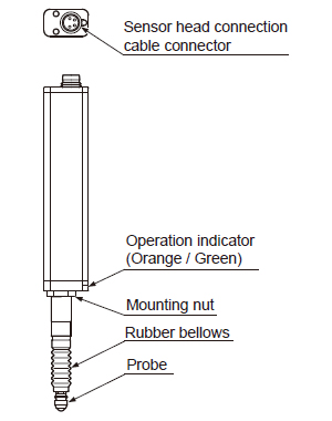
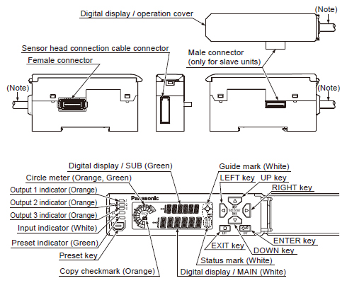
Part description
<Standard type>
(HG-S1010 / HG-S1110) |
|---|
 |
|
|
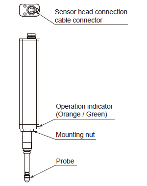
<Low measuring force type>
(HG-S1010R / HG-S1110R) |
|---|
 |
|
|
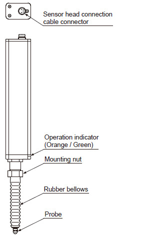
<Standard type>
(HG-S1032) |
|---|
 |
|
|
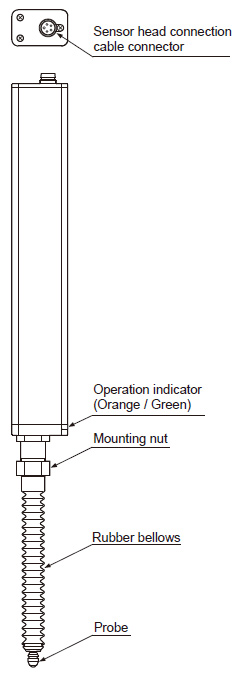
<Standard type>
(HG-S1050) |
|---|
 |
|
|
 |
| Note: Not provided on slave units or wire-saving type (HG-SC113). |
|
Sensor head (Air-Driven Type)
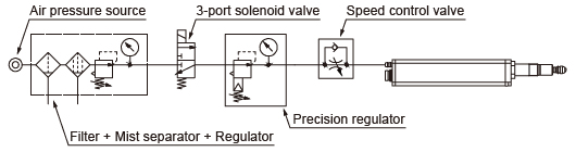
Air circuit (recommended)
| ・ |
When using air-driven type sensor heads (HG-S1010-AC, HG-S1110-AC), configure an air circuit similar to the one shown in the diagram below, and adjust the spindle speed using the speed control valve as needed. |
 |
| Notes :
| 1) |
Supply clean air (free from moisture, oil, dust, or other foreign objects) to this product. |
| 2) |
Air pressure may decrease, depending on the length of the air pipe from the air supply source or any pneumatic components (such as needle valves, speed controllers, or mini-filters) that are added. Take care to ensure that air pressure supply to the product is sufficient. Select pneumatic components suitable for the supplied air pressure. |
| 3) |
The 3-port solenoid valve and speed control valve have their respective mounting directions. Mount each valve in their correct direction by referring to the diagram on the left. |
| 4) |
A filter with a rated filtration of 5 μm 0.197 mil or less and a mist separator with a rated filtration of 0.3 μm 0.012 mil or less are recommended. |
|
|
Sensor head
Mounting
| ・ |
When tightening the nut, take care not to damage the rubber bellows. |
| ・ |
If the rubber bellows is deformed, a load will occur when the spindle operates and damage may result. |
| ・ |
Do not remove the rubber bellows from the standard type products (HG-S1010 / HG-S1110 / HG-S1032 / HG-S1050) except for when replacing them. Unnecessary removal of rubber bellows can result in entry of dust and water, thus causing malfunction. |
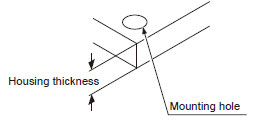
| 1. |
Open a hole in the housing in which the sensor head will be mounted. |
|
|
|
Mounting hole |
Housing thickness |
| HG-S1010(R), HG-S1110(R) |
ø8H7( +0.0150 )mm |
6.5~12.5mm |
| HG-S1032 |
ø12H7( +0.0180 )mm |
6.5~10.5mm |
| HG-S1050 |
6.5~12.5mm |
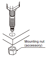
| 2. |
Insert the sensor head into the hole you opened in the housing, and fasten provisionally with the provided mounting nut.
Note:The orientation of the mounting nut depends on the thickness of the housing.
For details, refer to "Demensions" |
|
|
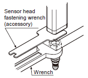
| 3. |
Fasten the sensor head.
When fastening the sensor head, tighten the mounting nut with a wrench while holding the sensor head in place with the provided sensor head fastening wrench as shown right.
Tighten to a torque of 12.5 N·m or less. (HG-S1032 / HG-S1050 : 15 N·m or less) |
|
|
| 4. |
Make sure that the rubber bellows has not become deformed as shown right.
If the rubber bellows is deformed, restore the normal shape by rotating the bellows or otherwise. |
|
|
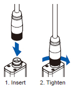
| Attaching the sensor head connection cable |
| ・ |
When disconnecting, always make sure that the fastening ring has been completely loosened before pulling out the cable. |
| ・ |
Risk of damage if you pull the cable with excessive force (15 N or more) with the fastening ring tightened. |
| 1. |
Insert the sensor head connection cable into the connector for the sensor head connection cable on the sensor head. |
| 2. |
Turn the fastening ring on the sensor head connector in the direction shown to fasten the ring. |
|
|
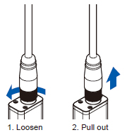
| 1. |
Turn the fastening ring on the sensor head connector in the direction of the arrow to loosen the ring. |
| 2. |
Grasp the sensor head connector and pull up to remove. |
|
|
Controller
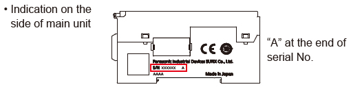
How to identify newer and older controllers, and combinations with sensor heads
- Air-driven type sensor heads and HG-S1050 must be used in combination with HG-SC□ controllers manufactured in or after February 2019.
- If the HG‑SC□ controller is used together with the HG‑TC□ controller for thru-beam type digital displacement sensor HG-T series, make sure to use the HG-SC□ controller manufactured in or after February, 2019. Furthermore, connect the slaves units of the same series to the side closer to the master unit and the slave units of the other series to the far side.
- When connecting only HG-S series controllers, both newer and older controllers can be connected.
How to identify newer controllers (manufactured in or after
February 2019) |
 |
|
Combinations with sensor heads
| Combination |
Newer controller |
Older controller |
Manufactured in or
after February 2019 |
Manufactured in or
before January 2019 |
| HG-SC□ |
HG-SC□ |
Sensor
head |
HG-S1010(R) |
Possible |
Possible |
| HG-S1110(R) |
| HG-S1032 |
| HG-S1050 |
Possible |
Not possible |
| |
Air-driven
type |
HG-S1010-AC |
Possible |
Not possible |
| HG-S1110-AC |
Please refer to the page below when using HG-S controllers and HG-T controllers connected.
>>With regards to the connected use of HG-S and HG-T
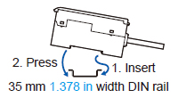
Mounting
| 1. |
Insert the rear of the mounting part into the DIN rail. |
| 2. |
While pressing down on the rear of the mounting part, insert the front of the mounting part into the DIN rail. |
|
|
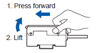
| 1. |
Grasp the product and push forward. |
| 2. |
Lift the front to remove. |
|
|
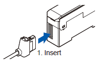
| Attaching the sensor head connection cable |
| 1. |
Insert the sensor head connection cable into the connector for the sensor head connection cable on the controller. |
|
|
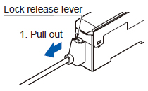
| 1. |
Grasp the controller, and while pressing on the lock release lever on the connector of the sensor head connection cable, pull toward you to disconnect. |
| Note: |
If you attempt to disconnect the cable by pulling it without pressing the lock release lever, cable wire breakage and connector damage may occur. |
|
|
Connection
| ・ |
Always shut off the power before connecting a slave unit to or disconnecting a slave unit from the master unit. Risk of controller damage if you attempt connection with the power on. |
| ・ |
Insert the male connector firmly into the female connector. Risk of controller damage if not completely connected. |
| ・ |
To connect units, the units must be mounted on a DIN rail. Attach end plates MS-DIN-E (optional) so as to enclose the connected units at the ends. |
| ・ |
Up to 15 slave units (up to 14 slave units when a communication unit for digital displacement sensor is connected) can be connected per master unit. |
| ・ |
When connecting slave units to a master unit, connect only NPN output types, or only PNP output types. Dissimilar output types cannot be connected together. |
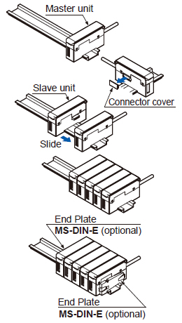
| 1. |
Mount one master unit on the DIN rail. |
| 2. |
Remove the connector cover. |
| 3. |
Mount each slave unit one at a time on the DIN rail. Remove all connector covers except for the cover on the end slave unit. |
| 4. |
Slide each slave unit to connect the female and male connectors. |
| 5. |
Attach end plates MS-DIN-E (optional) with the flat side facing in so as to enclose the connected units at the ends. |
| 6. |
Tighten the screws to fasten the end plates. |
|
|
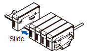
| 1. |
Loosen the screws on the end plates. |
| 2. |
Remove the end plates. |
| 3. |
Slide and remove the controllers, one at a time. |
|
|
Common
Wiring
| ・ |
The product is designed to fulfill the specifications when combined with the HG-S□ sensor head and HG-SC□ controller. If the product is used in combination with other products, it not only fails to meet the specifications but also generates a malfunction in some cases. |
| ・ |
For the controller DC power supply, only use a power supply that is isolated by means of an isolation transformer or otherwise. |
| ・ |
Risk of short-circuiting and damage to the controller or power supply if a transformer such as an auto transformer is used. Risk of short-circuiting and damage to the controller or power supply if incorrectly mounted or connected. |
- Make sure that the power supply is off while performing wiring or expansion work.
- After you have completed wiring work, check the wiring carefully before switching on the power.
- Do not run the wires together with high-voltage lines or power lines or put them in the same raceway. This can cause malfunction due to induction.
- Verify that the supply voltage fluctuations are within the rating.
- If power is supplied from a commercial switching regulator, ensure that the frame ground (F.G.) terminal of the power supply is connected to an actual ground.
- Do not use during the initial transient time after the power supply is switched ON.
- Make sure that stress by forcible bend or pulling is not applied directly to the sensor cable joint.
Others
- This device has been developed / produced for industrial use only.
- Do not use this product outside the range of the specifications. Risk of an accident and product damage. There is also a risk of a noticeable reduction of service life.
- This controller uses an EEPROM. The EEPROM has a service life of one million setting operations.
- This product is suitable for indoor use only.
- Avoid dust, dirt, and steam.
- Take care that the product does not come in direct contact with organic solvents such as thinner.
- Take care that the product does not come in direct contact with strong acid or alkaline.
- Take care that the product does not come in direct contact with oil or grease.
- Do not use in an environment containing inflammable or explosive gases.
- Performance may not be satisfactory in a strong electromagnetic field.
- This product is a precision device. Do not drop or otherwise subject to shock. Risk of product damage.
- Never attempt to disassemble, repair, or modify the product.
- Mount the sensor unit perpendicular to the measured surface. Mounting the sensor unit obliquely may not only result in measurement error but also significantly shorten its service life.
- Do not allow excessive horizontal force to be applied to the spindle. This may cause reduced accuracy and durability.
- Mount a pressure-reducing valve to use the product within the allowable working pressure range. Excessive pressure may result in failure or damage.
- Do not use air containing foreign objects (such as dust), water, or oil. Doing so may result in electric shock or failure. To prevent such problems, take appropriate measures such as mounting air filters or mist separators.
- Before performing maintenance, inspection, or cleaning, always shut off air supply completely and check that the pressure inside the product and piping is zero. Failure to do so may result in accidents or failures due to air pressure.
- Sensor head connection cable with L-shape connector CN-HS-C□L (optional) cannot be used with an air-driven type sensor head.
Return to top
Return to top

 Business
> Industrial Devices
> Automation Controls Top
> FA Sensors & Components
> Measurement Sensors
> Measurement Sensors
> Contact-Type Digital Displacement Sensor HG-S
> Cautions For Use
Business
> Industrial Devices
> Automation Controls Top
> FA Sensors & Components
> Measurement Sensors
> Measurement Sensors
> Contact-Type Digital Displacement Sensor HG-S
> Cautions For Use