【Notification of Manufacturer Change for Panasonic Industrial Devices SUNX Products and Panasonic Industrial Devices SUNX Tatsuno Products】
From April 1, 2024, the terms "Panasonic Industrial Devices SUNX Co., Ltd." and "Panasonic Industrial Devices SUNX Tatsuno Co., Ltd."
in this page and in the manuals and other documents to be downloaded will all be replaced with "Panasonic Industry Co., Ltd." and applied accordingly.

 Business
> Industrial Devices
> Automation Controls Top
> FA Sensors & Components
> Sensors
> Micro Photoelectric Sensors
> Amplifier Built-in / U-shaped Micro Photoelectric Sensor[Compact / Cable type] PM-45
Business
> Industrial Devices
> Automation Controls Top
> FA Sensors & Components
> Sensors
> Micro Photoelectric Sensors
> Amplifier Built-in / U-shaped Micro Photoelectric Sensor[Compact / Cable type] PM-45
Amplifier Built-in / U-shaped Micro Photoelectric Sensor[Compact / Cable type] PM-45
|
One step ahead in performance and mounting ease
|
 |
 |
 |
UL/C-UL
, CE
, UKCA
Approved
UL : Recognition
 December 2021 PM-45 series comply with ISO 13849-1 (Category 1, PLc) safety standards.
| * | Be sure to read the "Cautions For Use" when using for the above applications. |
|---|---|
| * | Before using this device, be sure to confirm the standards / regulations applied in the relevant nation and region. |
| * | If you need the Certificate or Confirmation Letter, please contact us. |
Features
Sensor unit complies with ISO 13849-1*1 Category 1 PLc*2.
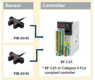
A Category 3 PLd Safety System can be built by using Category 4 PLe compliant controllers together with our sensors
*1 Safety-related parts of control systems, Part 1: General principles for design
*2 Conformed from December 2021 production.
■ Category 3, PLd construction example
 |
[Precautions when using as Category 3 PLd] |
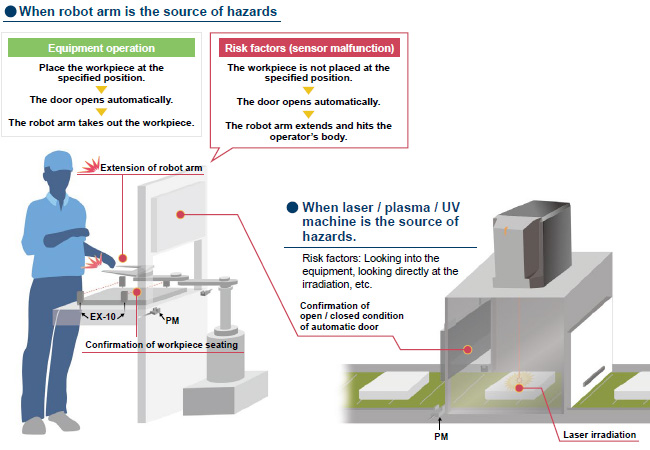
■ Application examples
[Required conditions]
| 1. | The source of hazards is located inside the machine and may cause hazards to nearby people. |
|---|---|
| 2. | The equipment is classified as Category 3 PLd or lower. |
| 3. | The source of hazards is isolated only by the automatic door. |
* The product can be used safely when all of the above conditions 1 through 3 are satisfied!
* There are cases where you can use it under other conditions.
|
| * | Be sure to read the "Cautions For Use" when using for safety applications. |
|---|
Three protection circuits standard on all models
All models are standardly equipped with the following protection circuits in their compact bodies. These protection circuits minimize the possibility of sensor malfunctions caused by erroneous wiring.
①.Reverse supply polarity protection circuit
②.Reverse output polarity protection circuit
③.Output short-circuit protection circuit
Industry’s first! IP64 rating
*As of April 2017, in-company survey.
Our original integrated molding method has eliminated grooves and gaps on the sensing surface and main body, thus reducing the possibility of malfunctions caused by splashing water or dust.
|

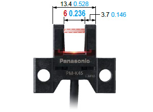
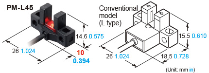
Ample beam emitting / receiving distance of 6 mm 0.236 in
The beam emitting and receiving sections are 0.5 mm 0.02 in thinner than those on our conventional models while their external dimensions are the same. As a result, the distance between the beam emitting point and receiving point increased by 1 mm 0.039 in. The wider distance means less possibility of collision between the sensing section and sensing object.
|
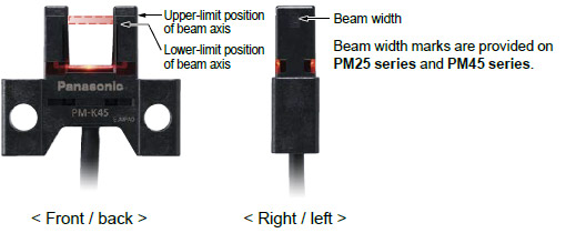
Beam marks for easy adjustment
The upper-limit and lower-limit positions of beam can be visually confirmed from the front, back, right and left sides of the sensor unit. This allows easy adjustment of the position of sensing object.
|
Large and easy to see
Multi-angle operation indicator
The large operation indicator (orange) lights up when the beam enters. The indicator is easy to see from above and from the sides.
Compact size
All new models require significantly less mounting space than our conventional models when mounted with the same pitch.
What's more, the new models can directly replace our conventional models currently in use.
|
All models easy to mount with M3 screws
The sensor unit can be installed with two M3 screws.
(M3 screws and washers are not included.)
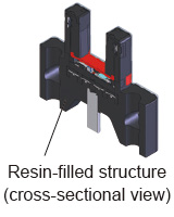
Resistant to vibrations and impacts
The sections where stress concentrates, such as the connecting section of the cable and internal circuit, are covered with a resin. This helps prevent malfunctions caused by vibrations and impacts.
|
BY EMAIL
- U.S.A.
- +1-800-344-2112
- Europe
- +49-89-45354-1000
- China
- +86-10-59255988
- Singapore
- +65-6299-9181


Requests to customers (Automation Control Components & Industrial Device) [Excluding specific product]
Requests to customers (Automation Control Components & Industrial Device) [For specific product]
Requests to customers (FA Sensors & Components [Excluding motors])
Requests to customers (Dedicated to industrial motors)
- COMPONENTS & DEVICES
- FA SENSORS & COMPONENTS
- Fiber Sensors
- Photoelectric Sensors / Laser Sensors
- Micro Photoelectric Sensors
- Light Curtains / Safety Components
- Area Sensors
- Inductive Proximity Sensors
- Particular Use Sensors
- Sensor Options
- Wire-Saving Systems
- Programmable Controllers / Interface Terminal
- Human Machine Interface
- Pressure Sensors / Flow Sensors
- Measurement Sensors
- Static Control Devices
- Laser Markers / 2D Code Readers
- Machine Vision System
- Energy Management Solutions
- Timers / Counters / FA Components
- MOTORS
![]()