------------------------------ Tab1 showing ------------------------------
Basic Information

One step ahead in performance and mounting ease


UL : Recognition
Three protection circuits standard on all models
All models are standardly equipped with the following protection circuits in their compact bodies. These protection circuits minimize the possibility of sensor malfunctions caused by erroneous wiring.
(1) Reverse supply polarity protection circuit
(2) Reverse output polarity protection circuit
(3) Output short-circuit protection circuit
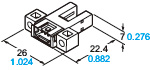
Ample beam emitting / receiving distance of 6 mm 0.236 in
The beam emitting and receiving sections are 0.5 mm 0.02 in thinner than those on our conventional models while their external dimensions are the same. As a result, the distance between the beam emitting point and receiving point increased by 1 mm 0.039 in. The wider distance means less possibility of collision between the sensing section and sensing object.
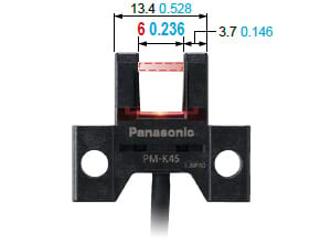
(Unit: mmin)
Note : The above image is PM-K45.
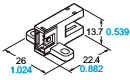
Beam marks for easy adjustment
The upper-limit and lower-limit positions of beam can be visually confirmed from the front, back, right and left sides of the sensor unit. This allows easy adjustment of the position of sensing object.
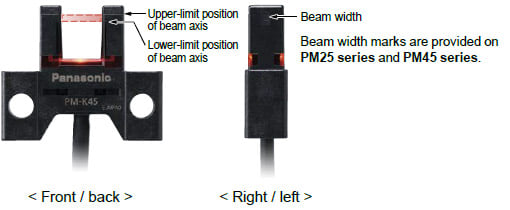
Note : The above image is PM-K45.
Large and easy to see
Multi-angle operation indicator
The large operation indicator (orange) lights up when the beam enters. The indicator is easy to see from above and from the sides.
All models easy to mount with M3 screws
The sensor unit can be installed with one or two M3 screws.(M3 screws and washers are not included.)
- Models requiring one M3 screw for installation : PM-F65, PM-R65
- Models requiring two M3 screws for installation : Models other than above
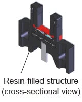
Resistant to vibrations and impacts
The sections where stress concentrates, such as the connecting section of the cable and internal circuit, are covered with a resin. This helps prevent malfunctions caused by vibrations and impacts.
------------------------------ Tab2 showing ------------------------------
Applications
Positioning of a pallet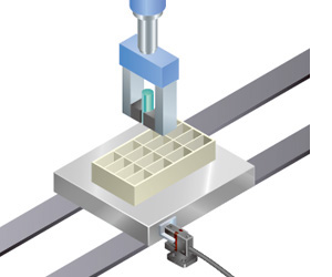
Pallet is stopped by sensing the dog*.
Sensing the starting point and overrun of a moving body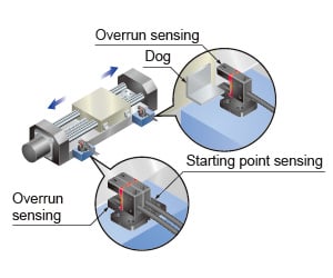
Starting point and overrun is sensed using the dog* on the base.
* "Dog" refers to the sensing object for activating the sensor's detecting operation.
Sensing the starting point on a rotating body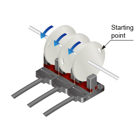
The starting point can be sensed by making a slit in the rotating body.
------------------------------ Tab3 showing ------------------------------
Order guide
Compact / Connector built-in type
| Type | Appearance (mm in) | Sensing range | Model No. | Output | Output operation |
|---|---|---|---|---|---|
| K type |
| 6 mm 0.236 in (fixed) | PM-K65 | NPN open-collector transistor | Incorporated with 2 outputs: Light-ON / Dark-ON |
| PM-K65-P | PNP open-collector transistor | ||||
| T type |
| PM-T65 | NPN open-collector transistor | ||
| PM-T65-P | PNP open-collector transistor | ||||
| PM-T65W | NPN open-collector transistor | |||
| PM-T65W-P | PNP open-collector transistor | ||||
| L type |
| PM-L65 | NPN open-collector transistor | ||
| PM-L65-P | PNP open-collector transistor | ||||
| Y type |
| PM-Y65 | NPN open-collector transistor | ||
| PM-Y65-P | PNP open-collector transistor | ||||
| F type |
| PM-F65 | NPN open-collector transistor | ||
| PM-F65-P | PNP open-collector transistor | ||||
| PM-F65W | NPN open-collector transistor | |||
| PM-F65W-P | PNP open-collector transistor | ||||
| R type |
| PM-R65 | NPN open-collector transistor | ||
| PM-R65-P | PNP open-collector transistor | ||||
| PM-R65W | NPN open-collector transistor | |||
| PM-R65W-P | PNP open-collector transistor |

Note :
PM-T65W is mounting-compatible with our conventional model "PM-T64W".
PM-F65W(-P) is mounting-compatible with our conventional model "PM-F54(P)".
PM-R65W(-P) is mounting-compatible with our conventional model "PM-R54(P)".
------------------------------ Tab4 showing ------------------------------
Option
| Designation | Model No. | Description | |
|---|---|---|---|
| Connector attached cable | CN-14A-C1 | Length: 1m 3.281 ft | 0.2 mm2 4-core cabtyre cable with connector on one end Cable outer diameter: ø3.7mm ø0.146 in |
| CN-14A-C2 | Length: 2m 6.562 ft | ||
| CN-14A-C3 | Length: 3m 9.843 ft | ||
| CN-14A-C5 | Length: 5m 16.404 ft | ||
| Connector attached cable (Flexible cable) | CN-14A-R-C1 | Length: 1m 3.281 ft | |
| CN-14A-R-C2 | Length: 2m 6.562 ft | ||
| CN-14A-R-C3 | Length: 3m 9.843 ft | ||
| CN-14A-R-C5 | Length: 5m 16.404 ft | ||
| Connector | CN-14A | Set of 10 housings and 40 contacts | |
Connector attached cable
CN-14A(-R)-C□
Connector
CN-14A
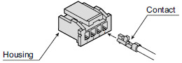
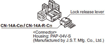
Recommended connector
Contact: SPHD-001T-P0.5, Housing: PAP-04V-S (Manufactured by J.S.T. Mfg. Co., Ltd.)
Note : Contact the manufacturer for details of the recommended products.
Recommended crimping tool
Model No. : YC-610R (Manufactured by J.S.T. Mfg. Co., Ltd.)
Note : Contact the manufacturer for details of the recommended products.
Recommended e-CON connector
Manufactured by 3M Japan Limited
Adapted connector : 37104-3122-000 FL
Please refer to "Introducing the 3M™ mini-clamp connector" for details.
------------------------------ Tab5 showing ------------------------------
Specifications
| Type | Compact / Connector built-in type | ||
|---|---|---|---|
| Mounting-compatible with conventional model (Note 2) | |||
| Model No. | NPN output | PM-□65 | PM-□65W |
| PNP output | PM-□65-P | PM-□65W-P | |
| Applicable regulations and certifications | CE Marking (EMC Directive, RoHS Directive), UKCA Marking (EMC Regulations, RoHS Regulations), UL/c-UL Recognition certification | ||
| Sensing range | 6 mm 0.236 in (fixed) | ||
| Minimum sensing object | 0.8 × 1.2 mm 0.031 × 0.047 in opaque object | ||
| Hysteresis | 0.05 mm 0.002 in or less | ||
| Repeatability | 0.01 mm 0.0004 in or less | ||
| Supply voltage | 5 to 24 V DC ±10 % Ripple P-P 10 % or less | ||
| Current consumption | 15 mA or less | ||
| Output | <NPN output type> NPN open-collector transistor ・Maximum sink current: 50 mA ・Applied voltage: 30 V DC or less (between output and 0 V) ・Residual voltage: 2 V or less (at 50 mA sink current), 1 V or less (at 16 mA sink current) <PNP output type> PNP open-collector transistor ・Maximum source current: 50 mA ・Applied voltage: 30 V DC or less (between output and + V) ・Residual voltage: 2 V or less (at 50 mA source current), 1 V or less (at 16 mA source current) | ||
| Output operation | Incorporated with 2 outputs: Light-ON / Dark-ON | ||
| Short-circuit protection | Incorporated | ||
| Response time | Under light received condition: 20 μs or less Under light interrupted condition: 80 μs or less (Maximum response frequency: 3 kHz) (Note 3) | ||
| Operation indicator | Orange LED (lights up under light received condition) | ||
| Pollution degree | 3 | ||
| Protection | IP40(IEC) | ||
| Ambient temperature | –25 to +55 ℃ –13 to +131 ℉ (No dew condensation or icing allowed), Storage: –30 to +80 ℃ –22 to +176 ℉ | ||
| Ambient humidity | 5 to 85 % RH, Storage: 5 to 95 % RH | ||
| Ambient illuminance | Fluorescent light: 1,000 ℓx at the light-receiving face | ||
| Voltage withstandability | 1,000 V AC for one min. between all supply terminals connected together and enclosure | ||
| Insulation resistance | 20 MΩ, or more, with 250 V DC megger between all supply terminals connected together and enclosure | ||
| Vibration resistance | 10 to 2,000 Hz frequency, 1.5 mm 0.059 in double amplitude (maximum acceleration 196 m/s2) in X, Y and Z directions for two hours each | ||
| Shock resistance | 15,000 m/s2 acceleration (1,500 G approx.) in X, Y and Z directions three times each | ||
| Emitting element | Infrared LED (Peak emission wavelength: 855 nm 0.034 mil, non-modulated) | ||
| Material | Enclosure: PBT, Display section: Polycarbonate | ||
| Cable length | Extension up to total 100 m 328.084 ft is possible with 0.3 mm2, or more, cable. (Note 4) | ||
| Weight | Net weight: 3 g approx., Gross weight: 3 g approx. | ||
Notes:
1) Where measurement conditions have not been specified precisely, the conditions used were an ambient temperature of +23 ℃ +73.4 ℉.
2) PM-T65W is mounting-compatible with our conventional model "PM-T64W".
PM-F65W(-P) is mounting-compatible with our conventional model "PM-F54(P)".
PM-R65W(-P) is mounting-compatible with our conventional model "PM-R54(P)".
3) The response frequency is the value when the disc, given in the figure below, is rotated.

4) If the cable is extended to 20 m 65.617 ft or longer, confirm that the supply voltage at the end of the cable attached to the sensor is 4.5 V or higher.
------------------------------ Tab6 showing ------------------------------
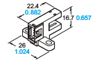
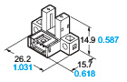
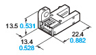
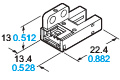
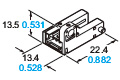
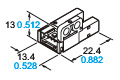
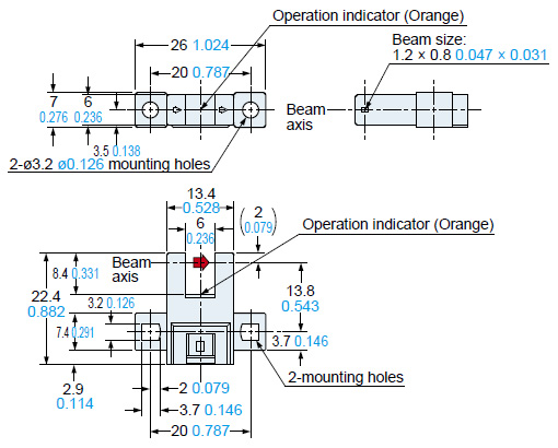
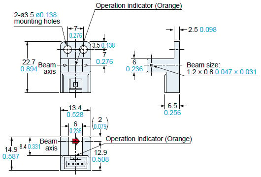
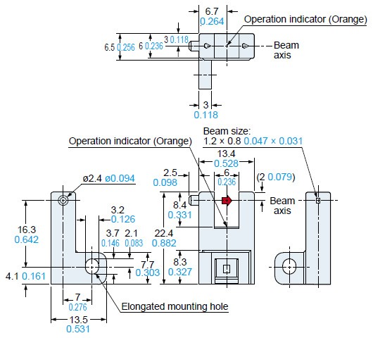
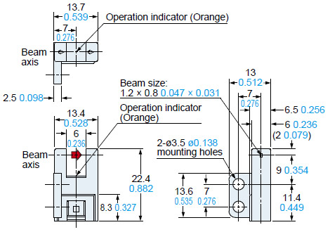
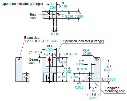
Dimensions
- Unit: mm in
PM-K65
PM-K65-P
Sensor
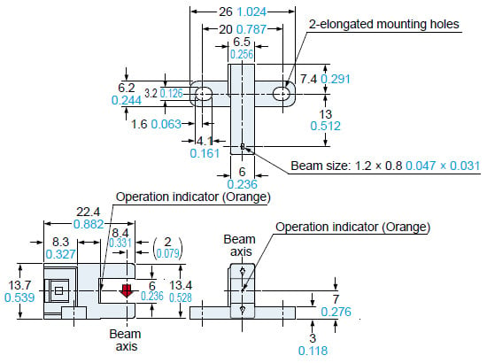
PM-T65
PM-T65-P
Sensor
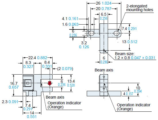
PM-T65W
PM-T65W-P
Sensor
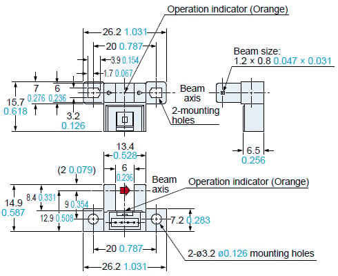
PM-L65
PM-L65-P
Sensor
PM-Y65
PM-Y65-P
Sensor
PM-F65
PM-F65-P
Sensor
PM-F65W
PM-F65W-P
Sensor
PM-R65
PM-R65-P
Sensor
PM-R65W
PM-R65W-P
Sensor

CN-14A-C□
CN-14A-R-C□
Connector attached cable (Optional)
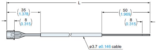
| Model No. | Length L |
|---|---|
| CN-14A(-R)-C1 | 1,000 39.370 |
| CN-14A(-R)-C2 | 2,000 78.740 |
| CN-14A(-R)-C3 | 3,000 118.110 |
| CN-14A(-R)-C5 | 5,000 196.850 |
------------------------------ Tab7 showing ------------------------------
I/O Circuit and Wiring diagrams
NPN output type
I/O circuit diagram
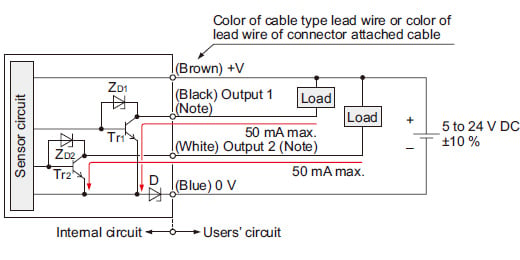
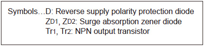
Note:
Ensure to insulate the unused output wire.
Output operation
| Color code | Output operation | |
|---|---|---|
| Output 1 | Black | Light-ON |
| Output 2 | White | Dark-ON |
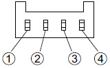
Terminal arrangement diagram
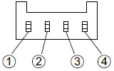
| Terminal No. | Designation |
|---|---|
| ① | + V |
| ② | Output 1: Light-ON |
| ③ | Output 2: Dark-ON |
| ④ | 0 V |
PNP output type
I/O circuit diagram
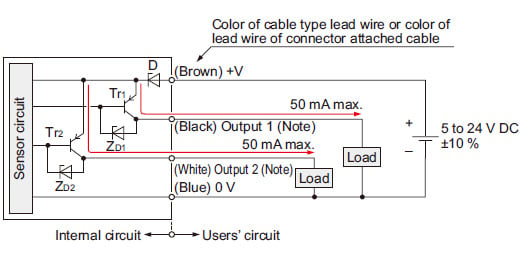
Note:
Ensure to insulate the unused output wire.
Output operation
| Color code | Output operation | |
|---|---|---|
| Output 1 | Black | Light-ON |
| Output 2 | White | Dark-ON |
Terminal arrangement diagram
| Terminal No. | Designation |
|---|---|
| ① | + V |
| ② | Output 1: Light-ON |
| ③ | Output 2: Dark-ON |
| ④ | 0 V |
------------------------------ Tab8 showing ------------------------------
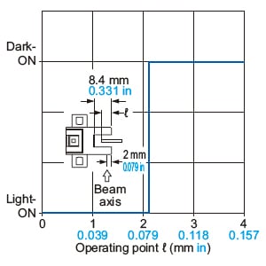
Sensing characteristics
*TYPICAL
Sensing position
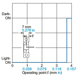
------------------------------ Tab9 showing ------------------------------
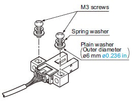
Mounting
| Screw | Spring washer | Flat washer | Tightening torque |
|---|---|---|---|
| M3 screw | 1 pc. | ø6 mm ø0.236 in (small round washer) | 0.5N・m |
- The following conditions must be observed when using screws to mount the sensor unit.
Cable extension
- Cable extension is possible up to an overall length of 100 m 328.084 ft with a 0.3 mm2, or more, cable. However, since a voltage drop shall occur due to the cable extension, ensure that the power supply voltage at the end of the connector attached cable of the sensor or at the sensor terminals is within the rating.
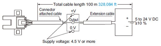
But, when the overall cable length, including the cable attached to the sensor, is as given below, there is no need to confirm the voltage.
| Conductor crosssection area of extension cable | Total cable length |
|---|---|
| 0.08 to 0.1 mm2 | Up to 5 m 16.404 ft |
| 0.2mm2 | Up to 10 m 32.808 ft |
| 0.3mm2 | Up to 20 m 65.617 ft |
Wiring
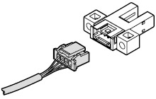
Connection method
- Insert the connector attached cable CN‑14A-C□ / CN‑14A-R-C□ in the connector part of this product as shown in the figure below.
<Connector pin position>
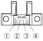
| Connector pin No. | ① | ② | ③ | ④ |
|---|---|---|---|---|
| Terminal designation | +V | Output 1 | Output 2 | 0V |
Disconnection method
Other
- This device has been developed / produced for industrial use only.
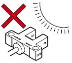
- Since the sensor is intended for use inside machines, no special countermeasures have been taken against extraneous light. Take care that extraneous light is not directly incident on the beam receiving section.
- Do not use during the initial transient time (50 ms) after the power supply is switched on.
- If the sensor is used in a place having excessive dust, periodically clean the emitting and receiving sections with a dry, soft cloth.
- If there is a large surge generating equipment, such as, motor, solenoid, electromagnetic valve, etc., in the vicinity of the sensor, use a surge absorber on that equipment. Further, do not run the sensor cables along power lines and use a capacitor between +V and 0 V, if required. Use the sensor after confirming that the surge has been eliminated.