
 Business
> Industrial Devices
> Automation Controls Top
> Components & Devices
> Relays / Couplers > Microwave Devices
> Microwave Devices Lineup
> RS Relays
> Cautions For Use
Business
> Industrial Devices
> Automation Controls Top
> Components & Devices
> Relays / Couplers > Microwave Devices
> Microwave Devices Lineup
> RS Relays
> Cautions For Use
RS Relays
-
Lineup
-
 RA Relays
1 GHz capable, 3 W carrying power (at 1 GHz), 50 Ω, 2 Form C relays
RA Relays
1 GHz capable, 3 W carrying power (at 1 GHz), 50 Ω, 2 Form C relays
-
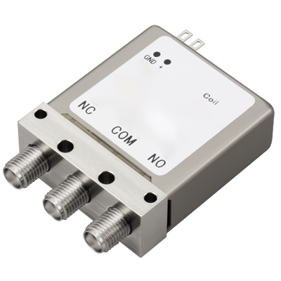 RD Coaxial Switches
26.5 GHz max. coaxial switches coming in SPDT, Transfer, and SP6T types
RD Coaxial Switches
26.5 GHz max. coaxial switches coming in SPDT, Transfer, and SP6T types
-
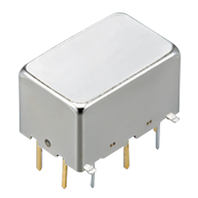 RJ Relays
8 GHz max. capable, 1 W carrying power ( at 5 GHz ), 50 Ω impedance and 2 Form C relays
RJ Relays
8 GHz max. capable, 1 W carrying power ( at 5 GHz ), 50 Ω impedance and 2 Form C relays
-
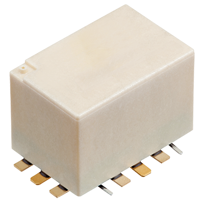 RN Relays
8 GHz max. capable, 150 W carrying power ( at 2 GHz ), compact SMD type, 50 Ω impedance and 1 Form C relays
RN Relays
8 GHz max. capable, 150 W carrying power ( at 2 GHz ), compact SMD type, 50 Ω impedance and 1 Form C relays
-
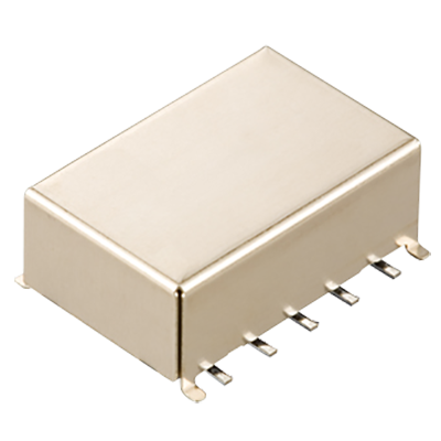
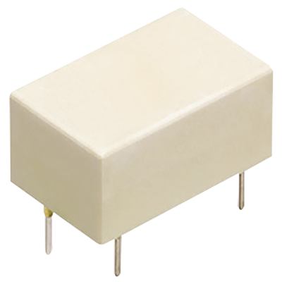 RS Relays
3 GHz capable, 10 W carrying power (at 3 GHz), 50/75 Ω, 1 Form C Relays
RS Relays
3 GHz capable, 10 W carrying power (at 3 GHz), 50/75 Ω, 1 Form C Relays
-
- CAD data Catalogs/Datasheets
- FAQ
|
RS Relays Cautions For Use
For general cautions for use, please refer to the "Relays Cautions For Use".
1.Coil operating power
Pure DC current should be applied to the coil. The wave form should be rectangular. If it includes ripple, the ripple factor should be less than 5%.
However, check it with the actual circuit since the characteristics may be slightly different. The nominal operating voltage should be applied to the coil for more than 30 ms to set/reset the latching type relay.
2.Coil connection
When connecting coils, refer to the wiring diagram to prevent mis-operation or malfunction.
3.External magnetic field
Since RS relays are highly sensitive polarized relays, their characteristics will be affected by a strong external magnetic field. Avoid using the relay under that condition.
4.Cleaning
For automatic cleaning, the boiling method is recommended. Avoid ultrasonic cleaning which subjects the relays to high frequency vibrations, which may cause the contacts to stick.
It is recommended that alcoholic solvents be used.
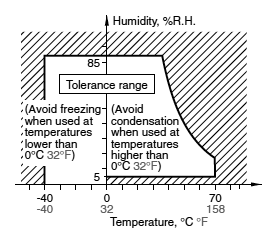
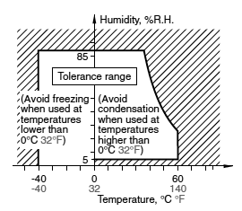
5.Conditions for operation, transport and storage conditions
1.Temperature
• Single side stable standard and latching type: –40 to 70°C –40 to 158°F
• Single side stable quiet type: –40 to 60°C –40 to 140°F
2.Humidity: 5 to 85% RH (Avoid freezing and condensation.)
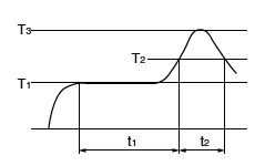
The humidity range varies with the temperature. Use within the range indicated in the graph below.
3.Atmospheric pressure: 86 to 106 kPa
Temperature and humidity range for usage, transport, and storage:
|
4.Condensation
Condensation forms when there is a sudden change in temperature under high temperature and high humidity conditions. Condensation will cause deterioration of the relay insulation.
5.Freezing
Condensation or other moisture may freeze on the relay when the temperature is lower than 0°C 32°F. This causes problems such as sticking of movable parts or operational time lags.
6.Low temperature, low humidity environments
The plastic becomes brittle if the relay is exposed to a low temperature, low humidity environment for long periods of time.
7.Storage requirements
Since the relay is sensitive to humidity, the surface-mount type is packaged with tightly sealed anti-humidity packaging. However, when storing, please be careful of the following.
- 1.Please use promptly once the antihumidity pack is opened. If relays are left as is after unpacking, they will absorb moisture which will result in loss of air tightness as a result of case expansion due to thermal stress when reflow soldering during the mounting process. (within one day, 30°C and 60%R.H or less)
- 2.When storing for a log period after opening the anti-humidity pack, storage in anti-humidity packaging with an antihumidity bag to which silica gel has been added, is recommended.
*Furthermore, if the relay is solder mounted when it has been subjected to excessive humidity, cracks and leaks can occur. Be sure to mount the relay under the required mounting conditions.
6.Soldering
1.Please meet the following conditions if this relay is to be automatically soldered.
(1) Preheating: Max. 120°C 248°F (terminal solder surface) for max. 120 seconds
(2) Soldering: Max. 260±5°C 500±9°F for max. 6 seconds
*Relays are influenced by the type of PC board used. Please confirm with the actual PC board you plan to use.
*Please avoid reflow soldering.
2.Surface-mount terminal
In case of automatic soldering, the following conditions should be observed.
(1) Position of measuring temperature
|
(2) IR (infrared reflow) soldering method
|
• Mounting cautions
Rise in relay temperature depends greatly on the component mix on a given PC board and the heating method of the reflow equipment. Therefore, please test beforehand using actual equipment to ensure that the temperature where the relay terminals are soldered and the temperature at the top of the relay case are within the conditions given above.
3.Please meet the following conditions if this relay is to be soldered by hand.
| (1) | 260°C 500°F for max. 10 seconds |
|---|---|
| (2) | 350°C 662°F for max. 3 seconds The effect on the relay depends on the actual substrate used. Please verify the substrate to be used. |
| (3) | Avoid ultrasonic cleaning. Doing so will adversely affect relay characteristics. Please use alcohol-based cleaning solvents when cleaning relays. |
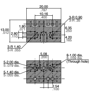
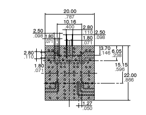
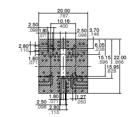
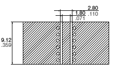
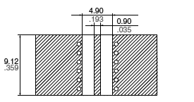
7.Tape and reel packing
1.Tape dimensions
|
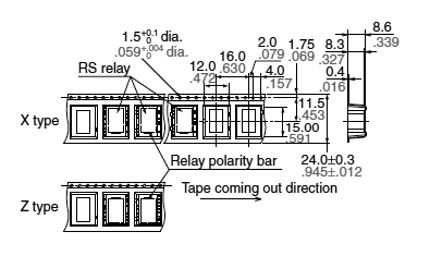
(General tolerance: ±0.1 ±.004)
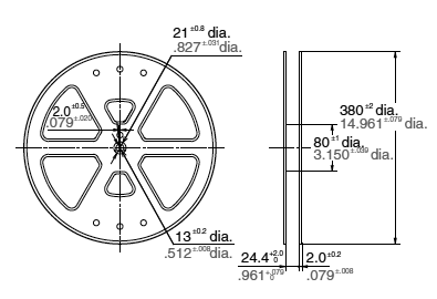
2.Dimensions of plastic reel
|
8.Measuring method
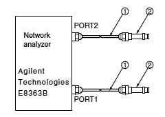
1.50Ω type
|
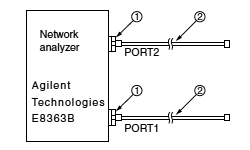
Connect connectors 1 and 2 respectively to PORT 1 and PORT 2. Perform calibration using the 3.5 mm calibration kit (HP85052B).
| No. | Product name | Contents |
|---|---|---|
| 1 | Agilent 85130-60011 |
Adapter 2.4mm-3.5mm female .095inch-.138inch female |
| 2 | SUHNER SUCOFLEX104 |
Cable 3.5mm-3.5mm male .138inch-.138inch male |
After calibration, connect the D.U.T. board and measure. However, connectors other than those for measurement should be connected with a 50Ω termination resistor.
|
|
|
|
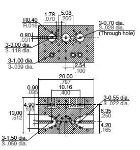
Material: Glass PTFE double-sided through hole PC board R-4737 (manufactured by our company)
Board thickness: t = 0.8 mm .031 inch
Copper plating: 18 μm
Connector (SMA type)
Product name: 01K1808-00 (Waka Manufacturing Co., Ltd.)
Insertion loss compensation:
The insertion loss of relay itself is given by subtracting the insertion loss of shortcircuit the Com and the NC (or NO). (signal path and two connectors)
2.75Ω type
|
Connect connectors 1 and 2 respectively to PORT 1 and PORT 2. Perform calibration using the 3.5 mm calibration kit (HP85039B).
| No. | Product name | Contents |
|---|---|---|
| 1 | 85134-60003 | Test port cable |
| 2 | 11852B | Conversion adapter; 50Ω N type (female) to 75Ω N type (male) |
| 2 | 85039-60011 | Conversion adapter; 75Ω N type (female) to 75Ω F type (male) |
After calibration, connect the D.U.T. board and measure. However, connectors other than those for measurement should be connected with a 75Ω termination resistor.
|
|
|
|
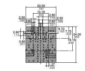
Material: Glass PTFE double-sided through hole PC board R-4737 (manufactured by our company)
Board thickness: t = 0.8 mm .031 inch
Copper plating: 18μm
Connector (F type receptacle)
Product name: C05-0236 (Komine Musen Electric Corporation)
Insertion loss compensation:
The insertion loss of relay itself is given by subtracting the insertion loss of shortcircuit the COM and the NC (or NO). (signal path and two connectors)
9.Others
1) The switching lifetime is defined under the standard test condition specified in the JIS* C 5442 standard (temperature 15 to 35°C 59 to 95°F, humidity 25 to 75%). Check this with the real device as it is affected by coil driving circuit, load type, activation frequency, activation phase, ambient conditions and other factors.
*JIS: Japanese Industrial Standards
Also, be especially careful of loads such as those listed below.
- When used for AC load-operating and the operating phase is synchronous, rocking and fusing can easily occur due to contact shifting.
- When high-frequency opening and closing of the relay is performed with a load that causes arcs at the contacts, nitrogen and oxygen in the air is fused by the arc energy and HNO3 is formed. This can corrode metal materials.
Three countermeasures for these are listed here.
(1) Incorporate an arc-extinguishing circuit.
(2) Lower the operating frequency
(3) Lower the ambient humidity
2) Use the relay within specifications such as coil rating, contact rating and on/off service life. If used beyond limits, the relay may overheat, generate smoke or catch fire.
3) Be careful not to drop the relay. If accidentally dropped, carefully check its appearance and characteristics before use.
4) Be careful to wire the relay correctly. Otherwise, malfunction, overheat, fire or other trouble may occur.
5) If a relay stays on in a circuit for many months or years at a time without being activated, circuit design should be reviewed so that the relay can remain non-excited. A coil that receives current all the time heats, which degrades insulation earlier than expected. A latching type relay is recommended for such circuits.
6) To ensure accurate operation of the latching type amidst surrounding temperature changes and other factors that might affect the set and reset pulse times, we recommend a coil impress set and reset pulse width of at least 30 ms at the rated operation voltage.
7) The latching type relay is shipped in the reset position. But jolts during transport or impacts during installation can change the reset position. It is, therefore, advisable to build a circuit in which the relay can be initialized (set and reset) just after turning on the power.
8) If silicone materials (e.g., silicone rubbers, silicone oils, silicone coating agents, silicone sealers) are used in the vicinity of the relay, the gas emitted from the silicone may adhere to the contacts of the relay during opening and closing and lead to improper contact. If this is the case, use a material other than silicone.
|
BY EMAIL


Requests to customers (Automation Control Components & Industrial Device) [Excluding specific product]
Requests to customers (Automation Control Components & Industrial Device) [For specific product]
Requests to customers (FA Sensors & Components [Excluding motors])
Requests to customers (Dedicated to industrial motors)
- COMPONENTS & DEVICES
- FA SENSORS & COMPONENTS
- Fiber Sensors
- Photoelectric Sensors / Laser Sensors
- Micro Photoelectric Sensors
- Light Curtains / Safety Components
- Area Sensors
- Inductive Proximity Sensors
- Particular Use Sensors
- Sensor Options
- Wire-Saving Systems
- Programmable Controllers / Interface Terminal
- Human Machine Interface
- Pressure Sensors / Flow Sensors
- Measurement Sensors
- Static Control Devices
- Laser Markers / 2D Code Readers
- Machine Vision System
- Energy Management Solutions
- Timers / Counters / FA Components
- MOTORS
![]()