
 Business
> Industrial Devices
> Automation Controls Top
> Components & Devices
> Relays / Couplers > High-capacity DC Cutoff Relay
> HE-V Relays
> Cautions For Use
Business
> Industrial Devices
> Automation Controls Top
> Components & Devices
> Relays / Couplers > High-capacity DC Cutoff Relay
> HE-V Relays
> Cautions For Use
HE-V Relays
-
Lineup
-
 EP Relays
High capacity of Max. 1,000 V DC Cut-off possible
EP Relays
High capacity of Max. 1,000 V DC Cut-off possible
-
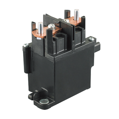
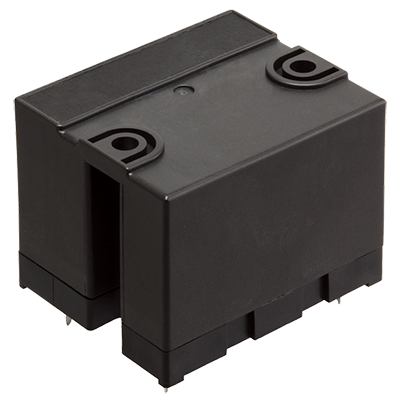 HE-V Relays
Max. 1,000 V DC, 20 A cut-off possible, High capacity DC power relays
HE-V Relays
Max. 1,000 V DC, 20 A cut-off possible, High capacity DC power relays
-
- CAD data Catalogs/Datasheets
- FAQ
|
HE-V Relays Cautions for Use
Usage, transport and storage conditions
1.Temperature:
–40 to +55°C –40 to +131°F (When coil holding voltage is 33 to 110%V)
–40 to +85°C –40 to +185°F (When coil holding voltage is 33% to 60%V)
2.Humidity: 5 to 85% RH (Avoid freezing and condensation.)
The humidity range varies with the temperature. Use within the range indicated in the graph.
3.Atmospheric pressure: 86 to 106 kPa
Temperature and humidity range for usage, transport, and storage
|
4.Condensation
Condensation forms when there is a sudden change in temperature under high temperature and high humidity conditions. Condensation will cause deterioration of the relay insulation.
5.Freezing
Condensation or other moisture may freeze on the relay when the temperatures is lower than 0°C 32°F. This causes problems such as sticking of movable parts or operational time lags.
6.Low temperature, low humidity environments
The plastic becomes brittle if the relay is exposed to a low temperature, low humidity environment for long periods of time.
Solder and cleaning conditions
1.Please obey the following conditions when soldering automatically.
(1) Preheating: Max. 120°C 248°F (solder surface terminal portion) and within 120 seconds
(2) Soldering iron: 260°C±5°C 500°F±41°F (solder temperature) and within 10 seconds (soldering time)
2.Please obey the following conditions when manual soldering.
Max. 260°C 500°F (solder temperature) and within 10 seconds (soldering time)
Max. 350°C 662°F (solder temperature) and within 3 seconds (soldering time)
*Effects of soldering heat on the relays vary depending on the PC board. So please confirm actual soldering condition with the PC board used for assembling.
3.Since this is not a sealed type relay, do not clean it as is. Also, be careful not to allow flux to overflow above the PC board or enter the inside of the relay.
Cautions for use
1.For precautions regarding use and explanations of technical terminology, please refer to our catalog.
2.To ensure good operation, please keep the voltage on the coil ends to ±5% (at 20°C 68°F) of the rated coil operation voltage. Also, please be aware that the pick-up voltage and drop-out voltage may change depending on the temperature and conditions of use.
3.Keep the ripple rate of the nominal coil voltage below 5%.
And do not have a parallel connection with diode for the purpose of coil surge absorber. Instead of diode, a Varistor is recommend for the absorber.
Recommended Varistor;
Maximum energy: more than 1J
Varistor voltage: 150 to 400% of nominal voltage
4.The cycle lifetime is defined under the standard test condition specified in the JIS C5442 standard (temperature 15 to 35°C 59 to 95°F, humidity 25 to 75%).
Check this with the real device as it is affected by coil driving circuit, load type, activation frequency, ambient conditions and other factors.
Especially, contact terminals have polarity. So if the contact terminals were connected with opposite pole, the electric life would be shorter.
5.This value can change due to the switching frequency, environmental conditions, and desired reliability level, therefore it is recommended to check this with the actual load.
6.Heat, smoke, and even a fire may occur if the relay is used in conditions outside of the allowable ranges for the coil ratings, contact ratings, operating cycle lifetime, and other specifications. Therefore, do not use the relay if these ratings are exceeded.
7.If the relay has been dropped, the appearance and characteristics should always be checked before use.
8.Incorrect wiring may cause unexpected events or the generation of heat or flames.
9.The relay should not be installed near strong magnetic field (transformers, magnets, etc.) and should not be installed near objects that radiate heat.
10.If the several relays are mounted closely or a heat-generation object is close to the relay, take care to check the abnormal temperature-rise and the insulation distance between the terminals outside of the relay.
11.If you are using an inductive load (L load) such that L/R > 1ms, add surge protection in parallel with the inductive load. If this is not done, the electrical life will decrease and cut-off failure may occur.
12.In case using a capacitive load (C-load), please take a countermeasure as pre-charging to the capacitive load so that the inrush current will not surpass 40A. The relay might have a contact welding without such countermeasure.
13.This relay is a high-voltage directcurrent switch. In its final breakdown mode, it may lose the ability to provide
the proper cut-off. Therefore, do not exceed the indicated switching capacity and life. (Please treat the relay as a product with limited life and replace it when necessary.)
In the event that the relay loses cut-off ability, there is a possibility that burning may spread to surrounding parts, so configure the layout so that the power is turned off within one second and from the point of view of safety, consider installing a failsafe circuit in the device.
14.Please carry out the design which had a enough margin in conductor width and a space between conductors in the case of a design of a printed circuit board.
15.Contact terminals have polarity. So if the contact terminals were connected with opposite pole, the electric life would be shorter. There is no polarity if they are used for power distribution only.
|
Related Information
BY EMAIL


Requests to customers (Automation Control Components & Industrial Device) [Excluding specific product]
Requests to customers (Automation Control Components & Industrial Device) [For specific product]
Requests to customers (FA Sensors & Components [Excluding motors])
Requests to customers (Dedicated to industrial motors)
- COMPONENTS & DEVICES
- FA SENSORS & COMPONENTS
- Fiber Sensors
- Photoelectric Sensors / Laser Sensors
- Micro Photoelectric Sensors
- Light Curtains / Safety Components
- Area Sensors
- Inductive Proximity Sensors
- Particular Use Sensors
- Sensor Options
- Wire-Saving Systems
- Programmable Controllers / Interface Terminal
- Human Machine Interface
- Pressure Sensors / Flow Sensors
- Measurement Sensors
- Static Control Devices
- Laser Markers / 2D Code Readers
- Machine Vision System
- Energy Management Solutions
- Timers / Counters / FA Components
- MOTORS
![]()