
 Business
> Industrial Devices
> Automation Controls Top
> Components & Devices
> Relays / Couplers
> Power Relays (Over 2A)
> Power Relays (Over 2A) Lineup
> HE Relays
> Option
Business
> Industrial Devices
> Automation Controls Top
> Components & Devices
> Relays / Couplers
> Power Relays (Over 2A)
> Power Relays (Over 2A) Lineup
> HE Relays
> Option
HE Relays
-
Lineup
-
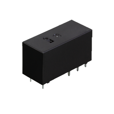
 DE Relays
Compliant with European safety standards, 1 Form A/2 Form A/1 Form A 1 Form B 10 A/8 A Polarized power relays
DE Relays
Compliant with European safety standards, 1 Form A/2 Form A/1 Form A 1 Form B 10 A/8 A Polarized power relays
-
 DJ Relays
High insulation, 1-pole/2-pole 16 A, Polarized power relays
DJ Relays
High insulation, 1-pole/2-pole 16 A, Polarized power relays
-
 DJ-H Relays
Suitable for lighting and motor load, 1 Form A 50 A, Latching relays
DJ-H Relays
Suitable for lighting and motor load, 1 Form A 50 A, Latching relays
-
 DK Relays
1 Form A 10 A, 1 Form A 1 Form B/2 Form A 8 A, Small polarized power relays
DK Relays
1 Form A 10 A, 1 Form A 1 Form B/2 Form A 8 A, Small polarized power relays
-
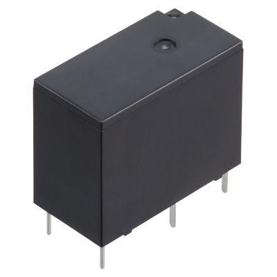
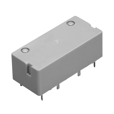
 DS Power Relays
1 Form A 8 A (AC) / 5 A (DC) , 1 Form A 1 Form B/2 Form A 5 A (AC/DC) , Small polarized power relays
DS Power Relays
1 Form A 8 A (AC) / 5 A (DC) , 1 Form A 1 Form B/2 Form A 5 A (AC/DC) , Small polarized power relays
-
 DW Relays
1 Form A 8 A/16 A, Small, Polarized power relays (latching type)
DW Relays
1 Form A 8 A/16 A, Small, Polarized power relays (latching type)
-
 DY Relays
1 Form A 10 A, 1 Form A 1 Form B 8 A, Small polarized power relays
DY Relays
1 Form A 10 A, 1 Form A 1 Form B 8 A, Small polarized power relays
-
 DZ-S Relays
IEC62055-31 UC3 compliant, 1 Form A 90 A, Power latching relays
DZ-S Relays
IEC62055-31 UC3 compliant, 1 Form A 90 A, Power latching relays
-
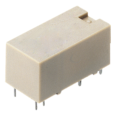
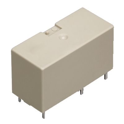
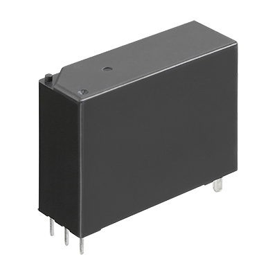
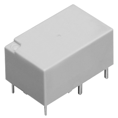
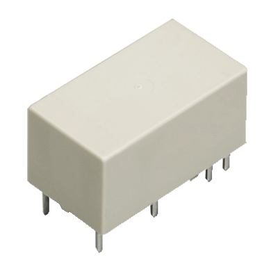
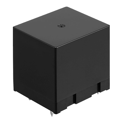
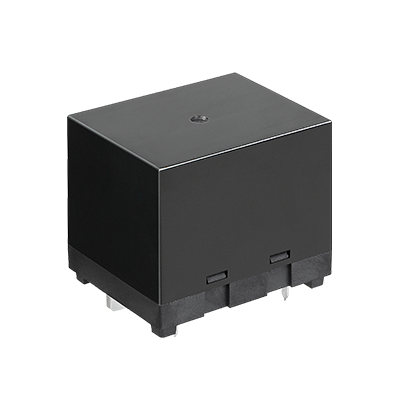
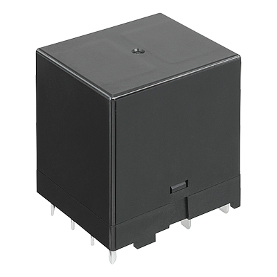
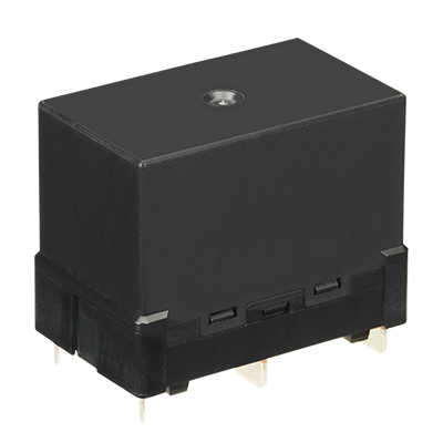
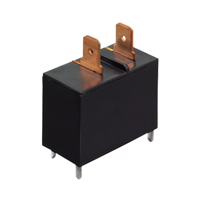
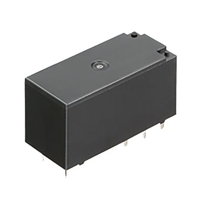
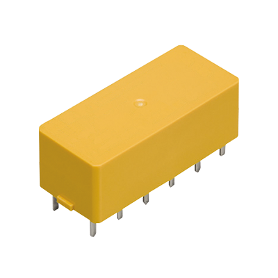
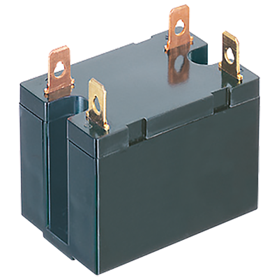 HE Relays
TV-10/TV-15 rated, 1 Form A 30 A, 2 Form A 25 A, Power relays
HE Relays
TV-10/TV-15 rated, 1 Form A 30 A, 2 Form A 25 A, Power relays
-
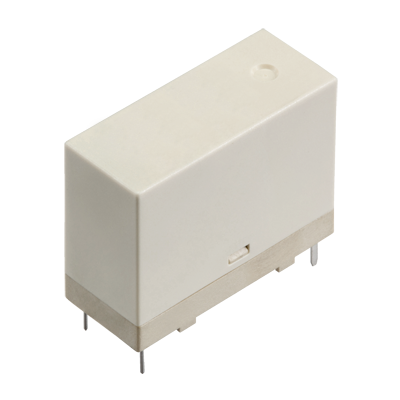
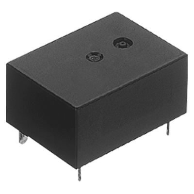
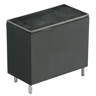
 HE Relays PV Type
Compact size, 1 Form A 35 A/48 A/90 A Power relays for solar inverter
HE Relays PV Type
Compact size, 1 Form A 35 A/48 A/90 A Power relays for solar inverter
-
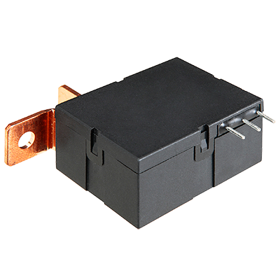
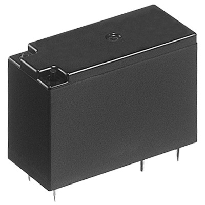
 HE-N Relays
High capacity 120 A 490 V AC 1 Form A power relay
HE-N Relays
High capacity 120 A 490 V AC 1 Form A power relay
-
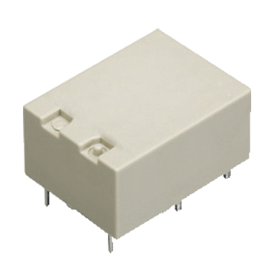
 HE-S Relays
Compact size 2a and 2a1b 40 A power relays for energy management and industrial equipment
HE-S Relays
Compact size 2a and 2a1b 40 A power relays for energy management and industrial equipment
-
 HE-R Relays
Compact size 2 Form A and 2 Form A 1Form B 80 A/4 Form A and 4 Form A and 1 Form B 40 A power relays
HE-R Relays
Compact size 2 Form A and 2 Form A 1Form B 80 A/4 Form A and 4 Form A and 1 Form B 40 A power relays
-
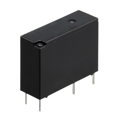
 JV-N Relays
1 Form A 16 A, low profile: 10.9 mm power relays for heater control
JV-N Relays
1 Form A 16 A, low profile: 10.9 mm power relays for heater control
-
 JW Relays
1 Form A/1 Form C/2 Form A/2 Form C, 5 A/10 A, Power relays
JW Relays
1 Form A/1 Form C/2 Form A/2 Form C, 5 A/10 A, Power relays
-
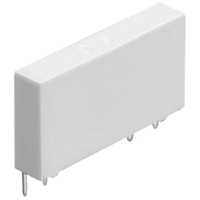
 LD-P Relays
Compliant with IEC/EN60335-1/ EN60079-15 (VDE approved) 1 Form A 5 A Slim power relays
LD-P Relays
Compliant with IEC/EN60335-1/ EN60079-15 (VDE approved) 1 Form A 5 A Slim power relays
-
 LF Relays
Ideal for compressor and inverter loads, 1 Form A 20 A, Power relays
LF Relays
Ideal for compressor and inverter loads, 1 Form A 20 A, Power relays
-
 LF-G Relays
Load for solar inverter, Compact size, 1 Form A 22 A/33 A, Power relays
LF-G Relays
Load for solar inverter, Compact size, 1 Form A 22 A/33 A, Power relays
-
 LQ Relays
Compliant with IEC/EN60335-1*1*2 /EN60079-15*3 (VDE approved) 1 Form A/1 Form C 10A small power relays
LQ Relays
Compliant with IEC/EN60335-1*1*2 /EN60079-15*3 (VDE approved) 1 Form A/1 Form C 10A small power relays
-
 LZ Relays
Low profile: 15.7 mm, 1 Form A/1 Form C 16 A, Power relay
LZ Relays
Low profile: 15.7 mm, 1 Form A/1 Form C 16 A, Power relay
-
 LZ-N Relays
EN60335-1 GWT compliant, 15.7 mm Low profile, 1 Form A/1 Form C 16 A, Power relays
LZ-N Relays
EN60335-1 GWT compliant, 15.7 mm Low profile, 1 Form A/1 Form C 16 A, Power relays
-
 NC Relays
Transistor drive, 2 Form C/4 Form C, 5 A Slim power relays
NC Relays
Transistor drive, 2 Form C/4 Form C, 5 A Slim power relays
-
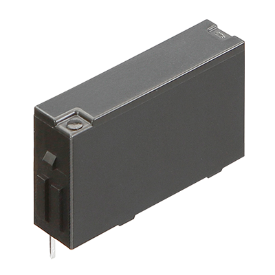 PA-N Relays
Complies with IEC61010 reinforced insulation, For PLC/Interface, 1 Form A 5 A, Slim power relay
PA-N Relays
Complies with IEC61010 reinforced insulation, For PLC/Interface, 1 Form A 5 A, Slim power relay
-
 PF Relays
Compliant with European standards, 1 Form A/1 Form C 6 A, Slim power relays
PF Relays
Compliant with European standards, 1 Form A/1 Form C 6 A, Slim power relays
-
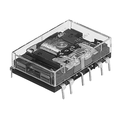
 S Relays
2 Form A 2 Form B/3 Form A 1 Form B/4 Form A /4 A Polarized power relays
S Relays
2 Form A 2 Form B/3 Form A 1 Form B/4 Form A /4 A Polarized power relays
-
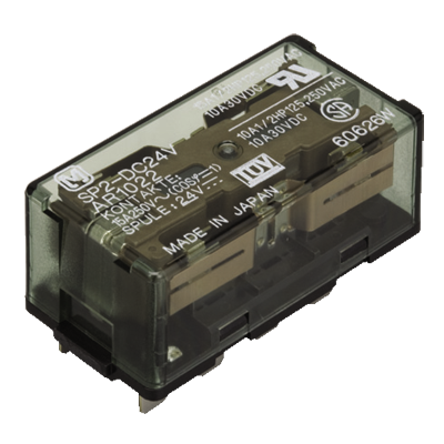 SP Relays
2 Form C 15 A, 4 Form C 10 A, Polarized power relays
SP Relays
2 Form C 15 A, 4 Form C 10 A, Polarized power relays
-
 ST Relays
1 Form A 1 Form B/2 Form A, 8 A, Polarized power relays
ST Relays
1 Form A 1 Form B/2 Form A, 8 A, Polarized power relays
-
- CAD data Catalogs/Datasheets
- FAQ
HE relays Terminal sockets
|
 |
 |
 |
Types
| Product name | Types No. | Part No. | Standard packing | |
|---|---|---|---|---|
| Inner carton | Case | |||
| 1 Form A | JH1-SF | AR58102 | 10 pcs. | 50 pcs. |
| 2 Form A | JH2-SF | AR58202 | 10 pcs. | 50 pcs. |
Rating
| Item | Specifications | ||
|---|---|---|---|
| Contact arrangement | 1 Form A | 2 Form A | |
| Dielectric strength (initial) | Each between terminals: 2,000 Vrms for 1 min (detection current: 10 mA) Between contacts – coil side: 5,000 Vrms for 1 min (detection current: 10 mA) |
||
| Insulation resistance (initial) | Each between terminals: Min. 100 MΩ (at 500 V DC, Measured portion is the same as the case of dielectric strength.) |
||
| Maximum carrying current | 30 A 250 V AC | 20 A 250 V AC | |
| Conditions for usage, transport and storage |
Ambient temperature: -50 to +55°C Humidity: 5 to 85% RH (Avoid icing and condensation) |
||
Handling
Mounting method of relay
|
|
|
Removing method of relay
|
Mounting to a DIN rail and Removing from a DIN rail
|
Guidelines for usage
- Be sure to tighten the screw-down terminals firmly. Loose terminals may lead to the generation of heat.
- When the 1 Form A is used in situations covered by the Japanese Electrical Appliance and Material Control Law, the use of 5.5 mm2 cabling and 30 A current is not allowed. Consequently, the circuit should be less than 20 A.
- When fixing the terminal socket with screws, to avoid torque damage and distortion, apply torque within the ranges shown below.
| M3.5 screw | 0.784 to 0.98 N·m (8 to 10 kgf·cm) |
|---|---|
| M4 screw | 1.176 to 1.37 N·m (12 to 14 kgf·cm) |
BY EMAIL


Requests to customers (Automation Control Components & Industrial Device) [Excluding specific product]
Requests to customers (Automation Control Components & Industrial Device) [For specific product]
Requests to customers (FA Sensors & Components [Excluding motors])
Requests to customers (Dedicated to industrial motors)
- COMPONENTS & DEVICES
- FA SENSORS & COMPONENTS
- Fiber Sensors
- Photoelectric Sensors / Laser Sensors
- Micro Photoelectric Sensors
- Light Curtains / Safety Components
- Area Sensors
- Inductive Proximity Sensors
- Particular Use Sensors
- Sensor Options
- Wire-Saving Systems
- Programmable Controllers / Interface Terminal
- Human Machine Interface
- Pressure Sensors / Flow Sensors
- Measurement Sensors
- Static Control Devices
- Laser Markers / 2D Code Readers
- Machine Vision System
- Energy Management Solutions
- Timers / Counters / FA Components
- MOTORS
![]()