
 Business
> Industrial Devices
> Automation Controls Top
> Components & Devices
> Switches
> Fall Detection Switches
> AHF2 (TiP) Switches
> Cautions For Use
Business
> Industrial Devices
> Automation Controls Top
> Components & Devices
> Switches
> Fall Detection Switches
> AHF2 (TiP) Switches
> Cautions For Use
AHF2 (TiP) Switches
-
Lineup
-
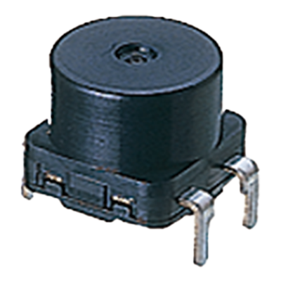 AHF2 (TiP) Switches
Small, Highly reliable Tilt Detection Switches Containing a Photo Sensor
AHF2 (TiP) Switches
Small, Highly reliable Tilt Detection Switches Containing a Photo Sensor
-
- CAD data Catalogs/Datasheets
- FAQ
|
AHF2 (TiP) Switches Cautions For Use
1.Handling
As indicated on the previous page, the absolute maximum rating
of the built-in photo-interrupter is 25°C.
In the enent that a voltage or current that exceeds the maximum
rating is applied to, or passed between the terminals, the photointerrupter
will no longer function normally. In such a case, do
not reuse the photo-interrupter but discard it.
Be careful not to apply an excessively large load to the terminals because this may damage the photo-interrupter.
2.Soldering
Perform soldering in less than 3 seconds with maximum 350°C iron. Care should be taken not to apply force to the terminals during soldering. We recommend a soldering iron with temperature adjustment in order to prevent poor quality soldering.
Please consult us if you intend to use a soldering iron of 60 W or higher.
3.Environment
This product is a non-contact type tip detection switch containing
a photo-interrupter.
It is intended for installation in equipment. Because of the nature
of a semiconductor, if this product is used continuously for a long
period in a high temperature, low temperature and/or humid
environment, according to the optic quantities decrease of
luminescent diode output characteristics may be significantly
affected. In such a case, take suitable measures, such as
inserting a comparator at the output side, to provide a greater
degree of margin with respect to change in the output
characteristics, and thereby improve the reliability of the product.
4.Preventing a malfunction
The TiP sensor uses an internal sphere, hence chattering occurs
if it is subjected to vibration or shock. To prevent chattering,
continuously read pulses of 30 ms max. using a microprocessor,
and set the microprocessor so that the switch goes L (ON) or H
(OFF) if the output level exceeds 500 ms continuously. Also, take
steps to keep induction and RF noise away from the sensor.
The switch should be mounted keeping away from the vibration
generator such as motor. Fix the PC board firmly in order to
prevent resonance with the vibration generator, or the contact
chattering of a switch may occur by the movement of a ball
inside.
The allowable vibration level which the chattering does not occur
would be less than 2.94m/s2 at 10 to 400Hz. (The range 260 to
320Hz may have a resonance point and the level should be less
than 0.98m/s2.)
|
5.others
- 1)Depending on the circuitry and the environmental conditions, solder migration may occur and short a circuit. Please confirm that the insulation distance is large enough in the actual application.
- 2)To prevent a malfunction, the switch should be kept away from the direct sunlight and any other light sources.
- 3)The noises caused by electrostatics, surge voltage and inductives may break the photo-interruptor.
- 4)The reflow soldering and cleaning are not allowed.
- 5)The switch should be mounted with the tolerance ±3 degree.
6.Confirmations in the actual use.
Each items in this spec sheet was tested and confirmed independently at a certain duration. To get a higher reliability of the equipment, please confirm the switch quality with the actual load and environmental conditions before using.
|
Related Information
BY EMAIL


Requests to customers (Automation Control Components & Industrial Device) [Excluding specific product]
Requests to customers (Automation Control Components & Industrial Device) [For specific product]
Requests to customers (FA Sensors & Components [Excluding motors])
Requests to customers (Dedicated to industrial motors)
- COMPONENTS & DEVICES
- FA SENSORS & COMPONENTS
- Fiber Sensors
- Photoelectric Sensors / Laser Sensors
- Micro Photoelectric Sensors
- Light Curtains / Safety Components
- Area Sensors
- Inductive Proximity Sensors
- Particular Use Sensors
- Sensor Options
- Wire-Saving Systems
- Programmable Controllers / Interface Terminal
- Human Machine Interface
- Pressure Sensors / Flow Sensors
- Measurement Sensors
- Static Control Devices
- Laser Markers / 2D Code Readers
- Machine Vision System
- Energy Management Solutions
- Timers / Counters / FA Components
- MOTORS
![]()