
 Business
> Industrial Devices
> Automation Controls Top
> FA Sensors & Components
> Timers / Counters / FA Componets
> Counters
> LC4H-W Electronic Counters(DIN 48)
Business
> Industrial Devices
> Automation Controls Top
> FA Sensors & Components
> Timers / Counters / FA Componets
> Counters
> LC4H-W Electronic Counters(DIN 48)
LC4H-W Electronic Counters(DIN 48)
|
Discontinuation plan
|
|
Electronic counters with two-step preset function
|


 |
 |
 |
UL/C-UL
, CE
, UKCA
Approved
Features
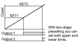
1.Two-stage presetting (upper and lower limits)
|
2.Bright and easy-to-read display
2-color backlight LCD display
3.Simple operation
Seesaw buttons
4.Short body of only 70.1 mm 2.760 in (Pin type) or 64.5 mm 2.539 in (Screw type)
5.IP66 compliant for resistance against negative environmental influences (only when panel surface uses rubber packing)
Setting The Operation Mode and Counter
1.Setting the output mode (output 1, 2)
|
2.Setting the set value
Set the set value with the UP keys on the front of the counter.
[Front display section]
|
|
| *Note: | Pressing the [SET/LOCK] key switches the display between the set value 1 and 2 displays. Display either set value [1] or [2], and set the value. |
|---|
3.Setting the input mode
Set the input mode using the key and switch in the front display section on the counter front.
- 1.Hold down the SET/LOCK key and press the UP key for the first digit. The setting mode is accessed.
|
- 2.Now release the SET/LOCK key.
- 3.Press the UP key for the first digit and the input position changes counterclockwise.
|
- 4.Press the RESET key and the input mode being displayed is set. The display then goes back to normal.
4.Checking the input mode
Hold down the SET/LOCK key and press the UP key for the second digit. The input mode is displayed for about 2 seconds and then the display goes back to normal. (During these 2 seconds, all operations other than the display are being performed.)
5.Locking the keys
Hold down the SET/LOCK key and press the UP key for the sixth digit. The keys will lock. This means that the UP and RESET keys do not respond to touch. To unlock the keys,hold down the SET/LOCK key and press the UP key for the sixth digit again.
| * | The input mode, maximum counting speed and minimum reset signal width cannot be preset independently for Setting 1 and Setting 2 |
|---|
6.Selecting the Setting 1 or Setting 2 display
Press the SET/LOCK key and the display changes between Setting 1 and Setting 2. (This operation does not affect overall operation.)
7.Changing the setting
1.While the counter is working, the UP key can be used to change the setting. Keep the following points in mind, however.
- 1. Suppose that a preset count-up value is smaller than the displayed count value. The counter counts up to the full scale mark (999999), goes back to "0", and counts up again to the preset number. When the preset count-up value is larger than the displayed count value, the counter counts up to the preset value.
- 2. Suppose that the counter is preset to count down. Whether a preset count-down value is smaller or larger than the count value, the counter counts down to "0".
2.When the preset value is "0", the counter does not start in the count-up mode. It starts counting up when the count value comes to "0" again.
- 1.Up-count input
The counter counts up to the full scale mark (999999), goes back to "0" and starts counting up again. - 2.Down-count input
The counter counts down to the full scale mark (--99999) and the display reads [ - - - - - -]. The count value does not become "0" and so the counter does not count up. - 3.Direction input, individual input, and phase input The preset value is counted up or down to any number other than "0" once. When it comes to "0" again, the counter starts counting up.
Operation Mode
1.Input mode
- 1.For the input mode, you can choose one of the following five modes
- Addition [UP]
- Subtraction [DOWN]
- Directive [DIR]
- Independent [IND]
- Phase [PHASE]
- 2.After the counter has been reset, setting 2 is displayed in the count-down mode. "0" appears instead in all other modes.
| Input mode | Operation | * Minimum input signal width 30 Hz: 16.7 ms; 5 kHz: 0.1 ms |
|---|---|---|
| Addition [UP] |
IN1 or IN2 works as an input block (gate) for the other input. | Example where IN1 is the counting input and IN2 is the input block (gate). Example where IN2 is the counting input and IN1 is the input block (gate).  * "A" must be more than the minimum input signal width. *n: Set value 2 |
| Subtraction [DOWN] |
||
| Directive [DIR] |
IN1 is the counting input and IN2 is the addition or subtraction directive input. IN2 adds at L level and subtracts at H level. |  * "A" must be more than the minimum input signal width. *n: Set value 2 |
| Independent [IND] |
IN1 is addition input and IN2 is subtraction input. |  * IN1 and IN2 are completely independent, so there is no restriction on signal timing. |
| Phase [PHASE] |
Addition when the IN1 phase advances beyond IN2, and subtraction when the IN2 phase advances beyond IN1. |  * "B" must be more than the minimum input signal width. |
2.Output mode
|
For the set value 1, you can choose one of the following four modes.
|
For the set value 2, you can choose one of the following eight modes.
|
Output mode for set value 1
| Output mode | Operation | (Example when input mode is either addition or subtraction) |
|---|---|---|
| Maintain output Over count I [HOLD-B] |
Output control is maintained after count-up completion and until resetting. However, counting is possible despite completion of count-up. |  * n: Set value 1 |
| Maintain output Over count II [HOLD-C] |
Output control is maintained after count-up completion and until the next signal enters. However, counting is possible despite completion of countup. |  * n: Set value 1 |
| Maintain output Over count III [HOLD-D] |
If the count value is greater than or equal to the preset value when counting up, the control output is held. The count operation is possible anyway. |  * n: Set value 1 |
| One shot Over count [SHOT-A] |
Output control is maintained after count-up completion for a fixed time (approx. 1 sec). Counting is possible despite completion of count-up. |  * n: Set value 1 |
Output mode for set value 2
| Output mode | Operation | (Example when input mode is either addition or subtraction) |
|---|---|---|
| Maintain output Hold count [HOLD-A] |
Output control is maintained after count-up completion and until resetting. During that time, the count display does not change from that at count-up completion. |  * n: Set value 2 |
| Maintain output Over count I [HOLD-B] |
Output control is maintained after count-up completion and until resetting. However, counting is possible despite completion of count-up. |  * n: Set value 2 |
| Maintain output Over count II [HOLD-C] |
Output control is maintained after count-up completion and until the next signal enters. However, counting is possible despite completion of countup. |  * n: Set value 2 |
| Maintain output Over count III [HOLD-D] |
If the count value is greater than or equal to the preset value when counting up, the counter starts counting up again. The count operation is possible anyway. |  * n: Set value 2 |
| One shot Over count [SHOT-A] |
Output control is maintained after count-up completion for a fixed time (approx. 1 sec). Counting is possible despite completion of count-up. |  * n: Set value 2 |
| One shot Recount I [SHOT-B] |
Output control is maintained after count-up completion for a fixed time (approx. 1 sec). Counting is possible despite completion of count-up. However, reset occurs simultaneous with completion of count-up. While output is being maintained, restarting of the count is not possible. |  * n: Set value 2 |
| One shot Recount II [SHOT-C] |
Output control is maintained after count-up completion for a fixed time (approx. 1 sec). Counting is possible despite completion of count-up. However, reset occurs simultaneous with output OFF. |  * n: Set value 2 |
| One shot Hold count [SHOT-D] |
Output control is maintained after count-up completion for a fixed time (approx. 1 sec). During that time, the count display does not change from that at count-up completion. Reset occurs simultaneous with output OFF. |  * n: Set value 2 |
|
| Note) | When control output 1 is on, the output mode of setting 2 (SHOT-A, B, C, D) is also on and output 1 changes as shown in the above table. |
|---|
3.Count-up
- 1.In control output 1, when the count value is equal to the preset value 1, it is counted. (However, if the output mode of the preset value 1 is HOLD-D, it is counted when the count value is greater than or equal to the preset value 1, regardless of the input mode.)
- 2.In control output 2, when the count value is equal to 0 in the count-down input mode, it is counted. In the other modes, when the count value is equal to the preset value 2, it is counted. (However, if the output mode of the preset value 2 is HOLD-D, it is counted when the count value is greater than or equal to the preset value 2, regardless of the input mode.)
- 3.It is not counted even when the counting conditions are satisfied right after resetting. It can be counted from when the count value changes.
BY EMAIL


Requests to customers (Automation Control Components & Industrial Device) [Excluding specific product]
Requests to customers (Automation Control Components & Industrial Device) [For specific product]
Requests to customers (FA Sensors & Components [Excluding motors])
Requests to customers (Dedicated to industrial motors)
- COMPONENTS & DEVICES
- FA SENSORS & COMPONENTS
- Fiber Sensors
- Photoelectric Sensors / Laser Sensors
- Micro Photoelectric Sensors
- Light Curtains / Safety Components
- Area Sensors
- Inductive Proximity Sensors
- Particular Use Sensors
- Sensor Options
- Wire-Saving Systems
- Programmable Controllers / Interface Terminal
- Human Machine Interface
- Pressure Sensors / Flow Sensors
- Measurement Sensors
- Static Control Devices
- Laser Markers / 2D Code Readers
- Machine Vision System
- Energy Management Solutions
- Timers / Counters / FA Components
- MOTORS
![]()