
 Business
> Industrial Devices
> Automation Controls Top
> FA Sensors & Components
> Timers / Counters / FA Componets
> Temperature Controllers
> KT7 Temperature Controllers
> Cautions For Use
Business
> Industrial Devices
> Automation Controls Top
> FA Sensors & Components
> Timers / Counters / FA Componets
> Temperature Controllers
> KT7 Temperature Controllers
> Cautions For Use
KT7 Temperature Controllers
|
Discontinuation plan
|
Cautions For Use
Mounting
• DIN rail mounting
Recommended DIN rail: Model No. ATA48011 |
 |
Part description
|
 Note: Color selection is the same for each size. |
Notes on site selection
This controller is intended to be used in the following environment (IEC 61010-1)
- Overvoltage category II and Pollution degree 2
Mount the controller in a place with:
- A minimum of dust, and an absence of corrosive gases
- No flammable, explosive gases
- Few mechanical vibrations or shocks
- No exposure to direct sunlight, an ambient temperature of -10 to 55 ℃ 14 to 131 ℉ that does not change rapidly. (When installing inside a panel, make particular allowance for heat dissipation. Avoid installation in situations such as above equipment that generates heat.)
- Locations in which temperature rapidly changes may cause condensation.
- Locations or atmospheres in which benzine, thinners, alcohol, or other organic solvents are present, or in which ammonia, sodium hydroxide, or other strong alkaline substances may adhere.
- Locations susceptible to direct impact or the transmission of vibrations, or where splashing with water is possible.
- In the proximity of equipment in which large switching surges occur or near high-voltage cables, high-voltage equipment, power lines, power equipment, ham radio transmitters, or equipment containing these or similar devices.
- An ambient non-condensing humidity of 35 to 85 % RH
- No large capacity electromagnetic switches or cables through which large current is flowing
- No water, oil or chemicals or where the vapors of these substances can come into direct contact with the controller
Notes on wiring
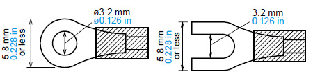
- The terminal block of KT4R / KT8R / KT9R / KT4H / KT4B series are designed to be wired from the left side (The terminal of KT2 series are designed to be wired from the upper and lower direction). The lead wire must be inserted from the left side of the terminal, and fastened by the terminal screw. Use a wirepressed terminal with insulation sleeve that fits to the M3 screw.
| Wire-pressed terminal |
Company name | Type name | Fastening torque |
|---|---|---|---|
| Fork type | NICHIFU Co., Ltd. | 1.25Y-3 | 0.6 N•m Max. 1.0 N•m. |
| J.S.T. Mfg. Co., Ltd. | VD1.25-B3A | ||
| Round type | NICHIFU Co., Ltd. | 1.25-3 | |
| J.S.T. Mfg. Co., Ltd. | V1.25-3 |
|
- Terminal screw fastening torque is 0.6 N·m to 1.0 N·m (for KT4R / KT8R / KT9R / KT4H / KT4B series). For KT7 series by M3 screw is less than 0.5 N·m and by M2 screw is less than 0.25 N·m respectively.
- Use a thermocouple and compensating lead wire according to the sensor input specification of the controller.
- Use a 3-wire system of RTD according to the sensor input specification of the controller.
- This controller has no built-in power switch, circuit breaker and fuse. Therefore, it is necessary to install them in the circuit near the external controller. (Recommended fuse: Time-lag fuse, rating voltage 250 V AC, rating current 2 A)
- In the case of 24 V AC / DC power supply, do not confuse the polarity when it is DC.
- With the relay contact output type, use the relay externally according to the capacity of the load to protect the built-in relay contact.
- When wiring, keep input wire (Thermocouple, RTD, etc.) away from power source wire and load wire.
- Turn the power supply to the instrument off before wiring or checking. Working or touching the terminal with the power switched on may result in electric shock which could cause severe injury or death.
- Do not drop wire chips into the holes of vent when wiring.
- To prevent the controller from harmful effects of unexpected high level noise, it is recommended that a surge absorber be installed between the electromagnetic switch coils.
Notes on mounting
- Do not use excessive force while screwing in the mounting frame and mounting bracket of KT4R / KT8R / KT9R / KT4H / KT4B series.
For KT8R / KT9R series, recommended torque is approximately 0.1 N·m.
For KT4H / KT4B series, recommended torque is approximately 0.05 to 0.06 N·m.
For KT4R series, recommended torque is approximately 0.15 N·m. - When mounting the KT7 series to the DIN rail, mount it in a lateral direction. Make sure a click is audible when fixed into place.
Optional heater burnout alarm output
(for KT7 / KT4H series)
- This alarm output is not available for detecting heater current under phase control.
- Use the current transformer (CT) provided, and pass one lead wire of the heater circuit into the hole of CT.
- When wiring, keep CT wire away from power source wire and load wire to avoid external interference.
- In three phase installations for KT4H series, ensure that R, S and T are each connected to a 2-line CT that connects with CT1 [(13) - (14)] and CT2 [(14) - (15)] terminals.
|
Please use rod terminals for the terminal portion of the KT7 series.
We recommend terminals made by Phoenix Contact.
(1) to (4) are AI0.25–8YE, AI0.34–8TQ,AI0.5–8WH, AI0.75–8GY, AI1.0–8RD,and AI1.5–8BK.
(5) to (9) are AI0.25–8YE, AI0.34–8TQ,and AI0.5–8WH.
The screw tightening torque for (1) to (4) should be less than 0.5 N·m and for
5) to (9) it should be less than 0.25N·m. Make sure no screw is loose.
BY EMAIL


Requests to customers (Automation Control Components & Industrial Device) [Excluding specific product]
Requests to customers (Automation Control Components & Industrial Device) [For specific product]
Requests to customers (FA Sensors & Components [Excluding motors])
Requests to customers (Dedicated to industrial motors)
- COMPONENTS & DEVICES
- FA SENSORS & COMPONENTS
- Fiber Sensors
- Photoelectric Sensors / Laser Sensors
- Micro Photoelectric Sensors
- Light Curtains / Safety Components
- Area Sensors
- Inductive Proximity Sensors
- Particular Use Sensors
- Sensor Options
- Wire-Saving Systems
- Programmable Controllers / Interface Terminal
- Human Machine Interface
- Pressure Sensors / Flow Sensors
- Measurement Sensors
- Static Control Devices
- Laser Markers / 2D Code Readers
- Machine Vision System
- Energy Management Solutions
- Timers / Counters / FA Components
- MOTORS
![]()