 Business
> Industrial Devices
> Automation Controls Top
> FA Sensors & Components
> Timers / Counters / FA Componets
> Temperature Controllers
> KT7 Temperature Controllers
> Wiring/ Connection
KT7 Temperature Controllers
|
Discontinuation plan
|
Wiring/ Connection
External Connection Diagram
|
| POWER SUPPLY | : | Power supply |
|---|---|---|
| OUT | : | Control output |
| RELAY | : | Relay contact output |
| V/A | : | DC voltage output / DC current output |
| EVT | : | Alarm output [Outputs when alarm, loop fault alarm or heater burnout alarm (optional) goes ON.] |
| TC | : | Thermocouple |
| RTD | : | Resistance temperature detector |
| DC | : | DC current or DC voltage |
| RS-485 | : | Serial communication |
| CT | : | CT input |
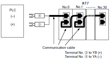
Communication Function Connection Diagram (PLC Connection Diagram)
|
CONTACT US
BY EMAIL
BY EMAIL
Please click your area to select country or region
Related Information
Service & Support
Requests to customers (Automation Control Components & Industrial Device) [Excluding specific product]
Requests to customers (Automation Control Components & Industrial Device) [For specific product]
Requests to customers (FA Sensors & Components [Excluding motors])
Requests to customers (Dedicated to industrial motors)
- COMPONENTS & DEVICES
- FA SENSORS & COMPONENTS
- Fiber Sensors
- Photoelectric Sensors / Laser Sensors
- Micro Photoelectric Sensors
- Light Curtains / Safety Components
- Area Sensors
- Inductive Proximity Sensors
- Particular Use Sensors
- Sensor Options
- Wire-Saving Systems
- Programmable Controllers / Interface Terminal
- Human Machine Interface
- Pressure Sensors / Flow Sensors
- Measurement Sensors
- Static Control Devices
- Laser Markers / 2D Code Readers
- Machine Vision System
- Energy Management Solutions
- Timers / Counters / FA Components
- MOTORS


