KW8M Eco-POWER METER (Discontinued Products)
We are sorry, the products have been discontinued. Please refer to the details of the discontinued products and the recommended substitutes list below.
 |
September 30, 2021 |
|
|
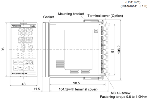
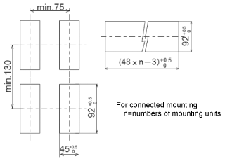
Dimensions
KW8M External Dimensions
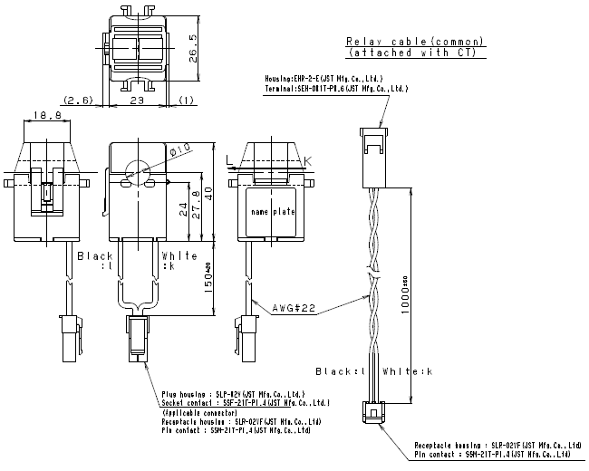
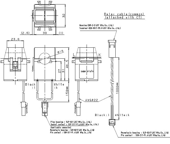
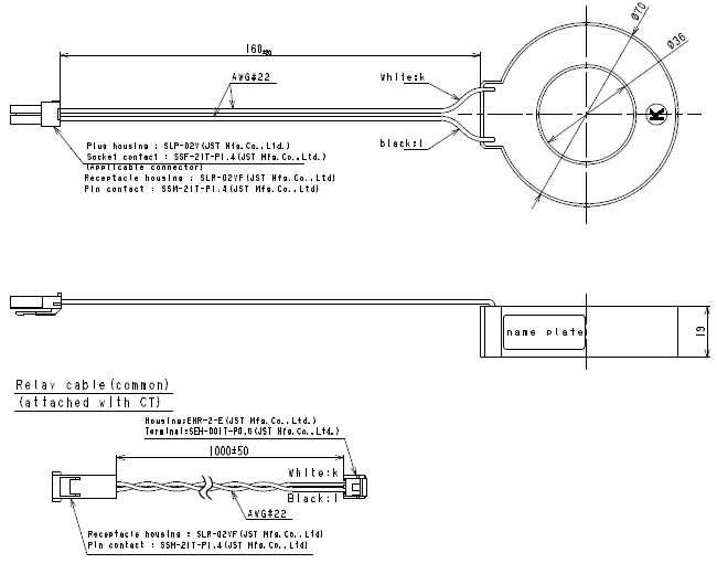
Dedicated current transformers CT
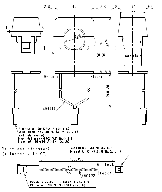
Dedicated current transformer (CT) Clamp-on type 5A/50A (AKW4801B)
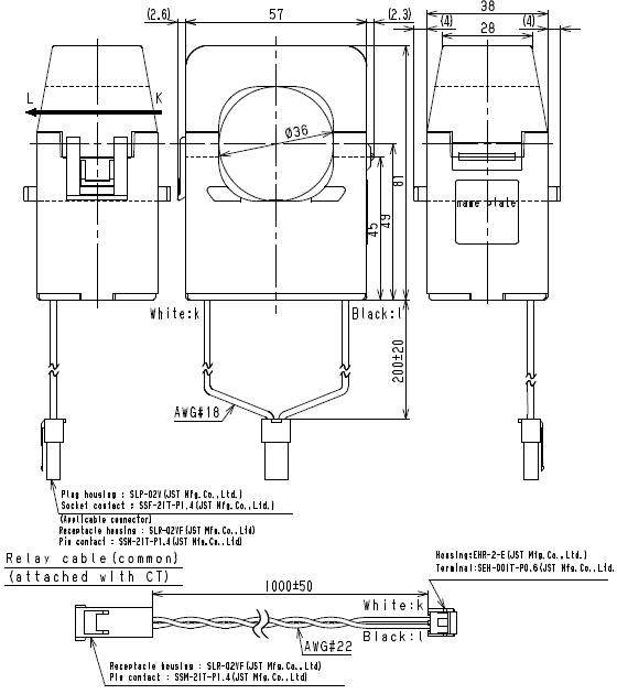
Dedicated current transformer (CT) Clamp-on type 100A (AKW4802B)
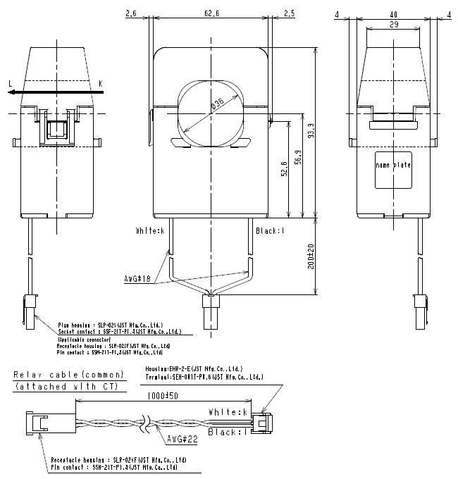
Dedicated current transformer (CT) Clamp-on type 250A (AKW4803B)
Dedicated current transformer (CT) Clamp-on type 400A (AKW4804B)
Dedicated current transformer (CT) Clamp-on type 600A (AKW4808B)
Return to top
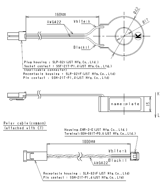
Dedicated current transformer (CT) Through type 50A/100A (AKW4506B)
Dedicated current transformer (CT) Through type 250A/400A/600A (AKW4507B/AKW4508B)
Return to top
Main unit terminal arrangement
| No. |
Function |
No. |
Function |
Terminal type |
| 1 |
N.C. |
11 |
P1 |
Measurement voltage input |
M3 screw
with
crossrecessed
/
slotted head |
| 2 |
Operating
power supply |
L |
12 |
P0 |
| 3 |
N |
13 |
P2 |
| 4 |
Pulse input |
+ |
14 |
P3 |
| 5 |
- |
15 |
CT1(+) |
Measurement CT input
(AKW8111 / AKW8111H)
Measurement current
input
(AKW8115) |
| 6 |
Pulse output |
+ |
16 |
CT1(-) |
| 7 |
- |
17 |
CT2(+) |
| 8 |
RS-485 |
+ |
18 |
CT2(-) |
| 9 |
- |
19 |
CT3(+) |
| 10 |
E |
20 |
CT3(-) |
| (Note): |
RS-485 (E) terminal is not an SG (signal ground) terminal. Do not connect it to the grounding wire of a shielded cable. |
Wiring Diagrams for AKW8111 and AKW8111H
Please connect a breaker (3 to 15A) to power supply and voltage input part for safety reasons and to
protect the device. Grounding the secondary side of VT (Voltage transformer) and CT (Current
transformer) is not necessary with low-voltage circuit.
When measuring a load with rated input voltage
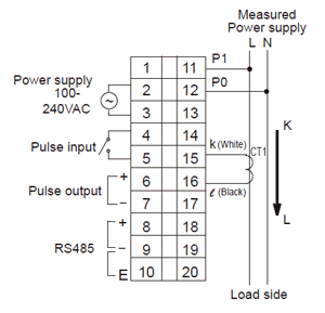
Single-phase two-wire system
*One current transformer (CT) is required to measure single-phase two-wire system. |
 |
|
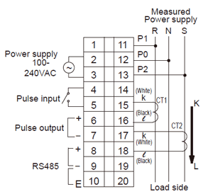
Single-phase three-wire
*Two CTs are required to measure single-phase three-wire system.
*Wire by diagram of single-phase 2-wire system when measure load using R-S with single-phase 3-wire
system.
|
 |
|
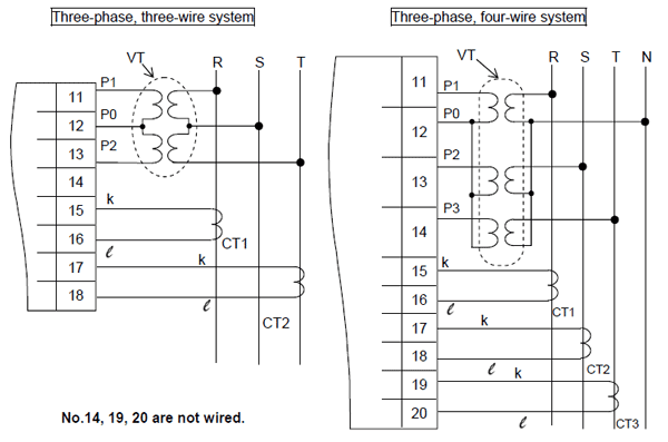
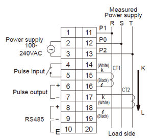
Three-phase three-wire system
*Two CTs are required to measure three-phase three-wire system.
|
 |
|
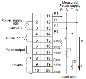
Three-phase four-wire system
*Three CTs are required to measure three-phase four-wire system.
|
 |
|
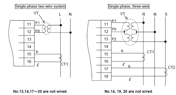
When measuring a load with exceed input voltage
Voltage transformer (VT) is needed when you measure a load with over rated input voltage (440V).Use VT, those secondary rating is 110V.
Grounding the secondary side of VT and CT is not necessary with low-voltage circuit.
|
 |
|
Wiring Diagrams for AKW8115
| ・ |
Please connect a breaker to the voltage input part for safety reasons and to protect the device. |
| ・ |
It is not necessary to ground secondary side of VT (voltage transformer) and CT (current transformer) with low-voltage circuit. |
| * |
When using the several CTs, each CT is separated as far as possible. If they are near it might not measure correctly by the interference of magnetic field. |
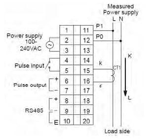
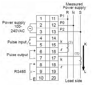
Single-phase two-wire system
*One current transformer (CT) is required to measure single-phase two-wire system.
|
 |
|
Single-phase three-wire
*Two CTs are required to measure single-phase three-wire system.
*Wire by diagram of single-phase 2-wire system when measure load using R-S with single-phase 3-wire
system.
|
 |
|
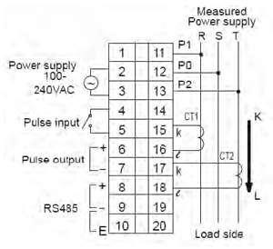
Three-phase three-wire system
*Two CTs are required to measure three-phase three-wire system.
|
 |
|
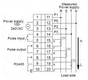
Three-phase four-wire system
*Three CTs are required to measure three-phase four-wire system.
|
 |
|
When measuring a load with exceed input voltage
Voltage transformer (VT) is needed when you measure a load with over rated input voltage (440V).Use VT, those secondary rating is 110V.
Grounding the secondary side of VT and CT is not necessary with low-voltage circuit.
|
 |
|
Caution for Wiring
| 1) |
Terminal fastening torque should be 0.6 to 1.0N・m. |
| 2) |
This has no built-in power switch, circuit breaker for power supply part. To protect the device, it is necessary to install power switch and circuit breaker in the power supply circuit.
And this has no built-in power switch, circuit breaker or fuse for measured voltage input parts.
Therefore it is necessary to install them in the circuit near this unit. |
| 3) |
The terminal block of KW8M is designed to be wired from left. Insert wires to the terminal from the left and fasten with terminal screws. |
| 4) |
In case using insulation sleeve, use an insulation sleeve applicable to M3 screw. Fastening torque
should be 0.6 to 1.0N・m. (Refer to the below.) |
| 5) |
We recommend a wire with the cross section of 0.75 to 1.25mm2 for power supply line and measured
voltage input line. |
| 6) |
Use flame-resistant cable for each wiring. |
Battery for Memory Backup (only for AKW8111H)
Battery is set to the unit AKW8111H, when shipping. Be sure to set the battery switch ON before starting the unit. It can backup the logging data and calendar time.
When starting to use the unit first or passing long time with battery OFF, initialize the memory by memory initialize mode (MODE4), or it can not indicate logging data correctly.
When to Replace Battery
Battery life is about 5 years (at 25℃).
However, using under high-temperature makes the life short.
When battery has abnormal or battery power is reduced, “E” is blinking in the bottom line.
Please replace the battery according to the procedures. |
 |
|
Return to top
Return to top
 Business
> Industrial Devices
> Automation Controls Top
> FA Sensors & Components
> Energy Management Solutions
> Eco Series (Simple Watt-Hour Meter/ Simple Power-On Counter/ Power-On Hour Meter)
> KW8M Eco-POWER METER(Discontinued Products)
> Dimensions


