
 Business
> Industrial Devices
> Automation Controls Top
> FA Sensors & Components
> Measurement Sensors
> Measurement Sensors
> High Accuracy Eddy Current Type Displacement Sensor GP-A(Discontinued Products)
> I/O Circuit and Wiring diagrams
Business
> Industrial Devices
> Automation Controls Top
> FA Sensors & Components
> Measurement Sensors
> Measurement Sensors
> High Accuracy Eddy Current Type Displacement Sensor GP-A(Discontinued Products)
> I/O Circuit and Wiring diagrams
High Accuracy Eddy Current Type Displacement Sensor GP-A (Discontinued Products)
|
We are sorry, the products have been discontinued. Please refer to the details of the discontinued products and the recommended substitutes list below.
|
|
I/O Circuit and Wiring diagrams
I/O circuit diagram
|
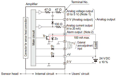
Notes:
| 1) | In case of using the analog voltage output, connect a device having a high input impedance. Also, take care that the output voltage is reduced due to the resistance of the wiring cable. |
|---|---|
| 2) | The alarm output is not incorporated with a short-circuit protection circuit. Do not connect it directly to a power supply or a capacitive load. |
| Symbols・・・ | D1: Input protection diode D2: Reverse supply polarity protection diode ZD: Surge absorption zener diode Tr : NPN output transistor |
|---|
Wiring diagram
|
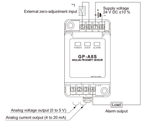
| Note: | After the wiring, make sure to fit the terminal covers. The terminal cover having a concave depression at the top should be fitted on the side having terminal Nos. 1 to 4. |
|---|
|
CONTACT US
If you have any questions, please select the option below to contact us or find answers.
CONTACT US
BY EMAIL
BY EMAIL
Please click your area to select country or region


Related Information
Service & Support
Requests to customers (Automation Control Components & Industrial Device) [Excluding specific product]
Requests to customers (Automation Control Components & Industrial Device) [For specific product]
Requests to customers (FA Sensors & Components [Excluding motors])
Requests to customers (Dedicated to industrial motors)
- COMPONENTS & DEVICES
- FA SENSORS & COMPONENTS
- Fiber Sensors
- Photoelectric Sensors / Laser Sensors
- Micro Photoelectric Sensors
- Light Curtains / Safety Components
- Area Sensors
- Inductive Proximity Sensors
- Particular Use Sensors
- Sensor Options
- Wire-Saving Systems
- Programmable Controllers / Interface Terminal
- Human Machine Interface
- Pressure Sensors / Flow Sensors
- Measurement Sensors
- Static Control Devices
- Laser Markers / 2D Code Readers
- Machine Vision System
- Energy Management Solutions
- Timers / Counters / FA Components
- MOTORS
![]()