
 Business
> Industrial Devices
> Automation Controls Top
> FA Sensors & Components
> Measurement Sensors
> Measurement Sensors
> Contact-Type Digital Displacement Sensor HG-S
> Specifications
Business
> Industrial Devices
> Automation Controls Top
> FA Sensors & Components
> Measurement Sensors
> Measurement Sensors
> Contact-Type Digital Displacement Sensor HG-S
> Specifications
Contact-Type Digital Displacement Sensor HG-S
|
Specifications
Sensor heads
Air-driven type • 10 mm 0.394 in type
| Type | Air-driven type • 10 mm 0.394 in type | ||||
|---|---|---|---|---|---|
| General purpose | High precision | ||||
| HG-S1010-AC | HG-S1110-AC | ||||
| With no seal cap mounted |
With no seal cap mounted |
||||
| Regulatory compliance |
CE Marking (EMC Directive, RoHS Directive), UKCA Marking (EMC Regulations, RoHS Regulations) | ||||
| Compatible controller (Note 2) |
HG-SC101(-P), HG-SC111(-P), HG-SC112(-P), HG-SC113 | ||||
| Position detection method |
Optical absolute linear encoder method | ||||
| Measurement range | 10 mm 0.394 in (Note 3) | ||||
| Stroke | 10.5 mm 0.413 in or more (Note 3) | ||||
| Measuring force (Note 4) |
Downward mount: (Note 5), Upward mount: (Note 5), Side mount: (Note 5) | ||||
| Resolution | 0.5 μm 0.02 mil | 0.1 μm 0.004 mil | |||
| Sampling cycle | 1 ms | ||||
| Indication accuracy (P-P) |
Full range: 2.0 μm 0.079 mil or less Limited range: 1.0 μm 0.039 mil or less (any 60 μm 2.362 mil) |
Full range: 1.0 μm 0.039 mil or less Limited range: 0.5 μm 0.02 mil or less (any 60 μm 2.362 mil) |
|||
| Tip deviation amount | 35 μm 1.378 mil (typical value) | ||||
| Hot swap function | Incorporated | ||||
| Working pressure range |
0.14 to 0.16 MPa |
0.035 to 0.045 MPa |
0.14 to 0.16 MPa |
0.035 to 0.045 MPa |
|
| Capacity to resist pressure |
0.2 MPa | ||||
| Usable fluid | Clean air (Dew point temperature: -10 ℃ +14 ℉ or less) | ||||
| Applicable tube | Outside diameter: ø4 mm ø0.157 in / Inside diameter: ø2.5 mm ø0.098 in | ||||
| Operation indicator | Equipped (2-color LED: Orange / Green) | ||||
| Pollution degree | 2 | ||||
| Operating altitude | 2,000 m 6561.68 ft or less (Note 6) | ||||
| Environmental resistance |
Protection | IP67 (IEC) (Note 7) | - | IP67 (IEC) (Note 7) | - |
| Ambient temperature |
-10 to +55 ºC +14 to +131 ℉ (No dew condensation or icing allowed), Storage: -20 to +60 ºC -4 to +140 ℉ |
||||
| Ambient humidity |
35 to 85 % RH, Storage: 35 to 85 % RH | ||||
| Insulation resistance |
100 MΩ or more at 250 V DC | ||||
| Vibration resistance |
10 to 500 Hz frequency, 3 mm 0.118 in double amplitude (10 to 58 Hz), maximum acceleration 196 m/s2, (58 to 500 Hz) in X, Y, and Z directions for two hours each | ||||
| Shock resistance |
1,960 m/s2 acceleration in X, Y, and Z directions three times each | ||||
| Grounding method | Capacitor grounding | ||||
| Material | Body: Zinc, Holder: Stainless steel, Spindle: Tool steel, Probe (Note 8): Brass (body) / Ceramic (ball), Air tube clamp: S60CM |
||||
| Weight | Net weight: 80 g approx. | ||||
| Accessories | Sensor head fastening wrench: 1 pc., Mounting nut: 1 pc., Seal cap: 1pc, Air tube clamp: 1 pc. |
||||
Notes :
| 1) | Where measurement conditions are not specified, the conditions used were as follows: standard type measurement probe (HG-SS10C), ambient temperature of +20 ℃ +68 ℉, and a clean atmosphere where water, oil, other liquids or dust does not come in contact with the equipment. |
|---|---|
| 2) | Be sure to use the sensor in combination with an HG-SC□ controller manufactured in or after February 2019. |
| 3) | The position that represents "0" as an absolute value is a position where the spindle is pushed further down from the bottom dead point by 0.1 mm 0.004 in or more. The term "stroke" indicates the total stroke length from the bottom dead point to the top dead point. |
| 4) | Measuring force changes with the air pressure used. Removing the seal cap enables the product to be used as the low measuring force type. |
| 5) | For the relationship between supplied air pressure and measuring force or between measuring force and pushed spindle position, see the figures below. For upward mount without a seal cap, subtract 0.2 N from the measuring force. For side mount, subtract 0.1 N from the measuring force. The following figures are only typical examples, and these relationships differ depending on the assembly accuracy of the product or the abrasion status of sealing materials.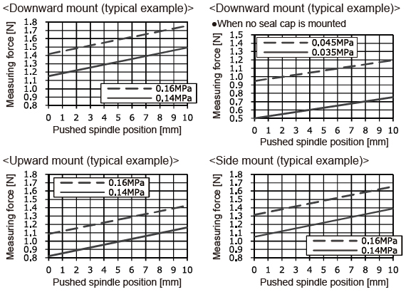 |
| 6) | Do not use or store in an environment that has been pressurized to an air pressure higher than the atmospheric pressure at 0 m. |
| 7) | Protective structure is not applicable when the sealing portions have deteriorated or become damaged. The protection level is zero when the seal cap is removed. |
| 8) | The probe is also available as an option. |
10 mm 0.394 in type
| Type | General purpose | High precision | |||
|---|---|---|---|---|---|
| Standard type | Low measuring force type |
Standard type | Low measuring force type |
||
| Model No. | HG-S1010 | HG-S1010R | HG-S1110 | HG-S1110R | |
| Regulatory compliance | CE Marking (EMC Directive, RoHS Directive), UKCA Marking (EMC Regulations, RoHS Regulations) | ||||
| Compatible controller | HG-SC101(-P), HG-SC111(-P), HG-SC112(-P), HG-SC113 | ||||
| Position detection method | Optical absolute linear encoder method | ||||
| Measurement range | 10 mm 0.394 in | ||||
| Stroke | 10.5 mm 0.413 in or more | ||||
| Measuring force (Note 2) |
Downward mount |
1.65 N or less 1.10 N (Note 3) |
0.35 N or less 0.30 N (Note 3) |
1.65 N or less 1.10 N (Note 3) |
0.35 N or less 0.30 N (Note 3) |
| Upward mount |
1.35 N or less 0.85 N (Note 3) |
- | 1.35 N or less 0.85 N (Note 3) |
- | |
| Side mount |
1.50 N or less 0.95 N (Note 3) |
0.25 N or less 0.20 N (Note 3) |
1.50 N or less 0.95 N (Note 3) |
0.25 N or less 0.20 N (Note 3) |
|
| Resolution | 0.5 μm 0.020 mil | 0.1 μm 0.004 mil | |||
| Sampling period | 1 ms | ||||
| Indication accuracy (P-P) |
Full range: 2.0 μm 0.079 mil or less Narrow range: 1.0 μm 0.039 mil or less (any 60 μm 2.362 mil) |
Full range: 1.0 μm 0.039 mil or less Narrow range: 0.5 μm 0.020 mil or less (any 60 μm 2.362 mil) |
|||
| Tip deviation amount | 35 μm 1.378 mil (typical)(Note 4) | ||||
| Hot swap function | Incorporated | ||||
| Operation indicator | 2-color LED (Orange / Green) | ||||
| Pollution degree | 2 | ||||
| Operating altitude | 2,000 m 6561.68 ft or less (Note 5) | ||||
| Environmental resistance |
Protection | IP67 (IEC) (Note 6) | - | IP67 (IEC) (Note 6) | - |
| Ambient temperature |
-10 to +55 ℃ +14 to +131 ℉ (No condensation or icing), Storage: -20 to +60 ℃ -4 to +140 ℉ |
||||
| Ambient humidity |
35 to 85 % RH, Storage: 35 to 85 % RH | ||||
| Insulation resistance |
100 MΩ or more at 250 V DC | ||||
| Vibration resistance |
10 to 500 Hz frequency, 3 mm 0.118 in double amplitude (10 to 58 Hz), maximum acceleration 196 m/s2, (58 to 500 Hz) in X, Y, and Z directions for two hours each | ||||
| Shock resistance |
1,960 m/s2 acceleration in X, Y and Z directions three times each | ||||
| Grounding method | Capacitor grounding | ||||
| Material | Body | Zinc | |||
| Holder | Stainless steel | ||||
| Spindle | Tool steel | ||||
| Probe (Note 7) | Brass (body) / Ceramic (ball) | ||||
| Rubber bellows | NBR (black) | ||||
| Weight | Net weight: 80 g approx. | ||||
| Accessories | Standard type (HG-S1010 / HG-S1110): Sensor head fastening wrench 1 pc., Mounting nut 1 pc. Low measuring force type (HG-S1010R / HG-S1110R): Sensor head fastening wrench 1 pc., Mounting nut 1 pc., Rubber bellows 1 pc. |
||||
Notes:
| 1) | Where measurement conditions have not been specified precisely, the conditions used were as follows: standard type measurement probe (HG‑SS10C), ambient temperature +20 ℃ +68 ℉, and a clean atmosphere where dust and liquids such as water and oil do not come in contact with the equipment. |
|---|---|
| 2) | In the case of low measurement force type (HG-S1010R / HG-S1110R), measurements were obtained with products in standard configuration without rubber bellows. |
| 3) | Typical value near center of measurement. |
| 4) | Value calculated from the clearance of the upper and lower plain bearings. |
| 5) | Do not use or store in an environment that has been pressurized to an air pressure higher than the atmospheric pressure at 0 m. |
| 6) | Excludes damage and deterioration to rubber bellows due to external causes. |
| 7) | The probes (optional) are also available. |
32 mm 1.260 in type
| Type | General purpose | ||
|---|---|---|---|
| Standard | |||
| Model No. | HG-S1032 | ||
| Regulatory compliance | CE Marking (EMC Directive, RoHS Directive), UKCA Marking (EMC Regulations, RoHS Regulations) | ||
| Compatible controller | HG-SC101(-P), HG-SC111(-P), HG-SC112(-P), HG-SC113 | ||
| Position detection method | Optical absolute linear encoder method | ||
| Measurement range | 32mm 1.260 in | ||
| Stroke | 32.5 mm 1.280 in or more | ||
| Measuring force | Downward mount |
2.97 N or less 1.90 N (Note 2) |
|
| Upward mount |
2.09 N or less 1.19 N (Note 2) |
||
| Side mount |
2.53 N or less 1.50 N (Note 2) |
||
| Resolution | 0.5μm 0.020 mil | ||
| Sampling period | 1ms | ||
| Indication accuracy (P-P) | Full range : 3.0 μm 0.118 mil or less Narrow range : 2.0 μm 0.079 mil or less (any 60 μm 2.362 mil) |
||
| Tip deviation amount | 40 μm 1.575 mil (typical)(Note 3) | ||
| Hot swap function | Incorporated | ||
| Operation indicator | 2-color LED (Orange / Green) | ||
| Pollution degree | 2 | ||
| Operating altitude | 2,000 m 6561.68 ft or less (Note 4) | ||
| Environmental resistance |
Protection | IP67 (IEC) (Note 5) | |
| Ambient temperature | -10 to +55 ℃ +14 to +131 ℉ (No condensation or icing), Storage: -20 to +60 ℃ -4 to +140 ℉ | ||
| Ambient humidity | 35 to 85 % RH, Storage: 35 to 85 % RH | ||
| Insulation resistance | 100 MΩ or more at 250 V DC | ||
| Vibration resistance | 10 to 150 Hz frequency, 3 mm 0.118 in double amplitude (10 to 58 Hz), maximum acceleration 196 m/s2, (58 to 150 Hz) in X, Y, and Z directions for two hours each | ||
| Shock resistance | 1,960 m/s2 acceleration in X, Y and Z directions three times each | ||
| Grounding method | Capacitor grounding | ||
| Material | Body | Aluminum alloy | |
| Holder | Stainless steel | ||
| Spindle | Free-cutting steel | ||
| Probe (Note 6) | Brass (body) / Ceramic (ball) | ||
| Rubber bellows | NBR (black) | ||
| Weight | Net weight: 150 g approx. | ||
| Accessories | Sensor head fastening wrench 1 pc., Mounting nut 1 pc. | ||
Notes:
| 1) | Where measurement conditions have not been specified precisely, the conditions used were as follows: standard type measurement probe (HG‑SS10C), ambient temperature +20 ℃ +68 ℉, and a clean atmosphere where dust and liquids such as water and oil do not come in contact with the equipment. |
|---|---|
| 2) | Typical value near center of measurement. |
| 3) | Value calculated from the clearance of the upper and lower plain bearings. |
| 4) | Do not use or store in an environment that has been pressurized to an air pressure higher than the atmospheric pressure at 0 m. |
| 5) | Excludes damage and deterioration to rubber bellows due to external causes. |
| 6) | The probes (optional) are also available. |
50 mm 1.969 in type
| Type | General purpose | ||
|---|---|---|---|
| Standard type | |||
| Model No. | HG-S1050 | ||
| Regulatory compliance | CE Marking (EMC Directive, RoHS Directive), UKCA Marking (EMC Regulations, RoHS Regulations) | ||
| Compatible controller (Note 2) |
HG-SC101(-P), HG-SC111(-P), HG-SC112(-P), HG-SC113 | ||
| Position detection method | Optical absolute linear encoder method | ||
| Measurement range | 50 mm 1.969 in | ||
| Stroke | 50.5 mm 1.988 in or more | ||
| Measuring force | Downward mount | 3.8 N or less (50 mm 1.969 in pressing position) 1.9 N (intermediate position) (Note 3) |
|
| Upward mount | 3.2 N or less (50 mm 1.969 in pressing position) 1.4 N (intermediate position) (Note 3) |
||
| Side mount | 3.4 N or less (50 mm 1.969 in pressing position) 1.7 N (intermediate position) (Note 3) |
||
| Resolution | 0.5 μm 0.020 mil | ||
| Sampling period | 1 ms | ||
| Indication accuracy (P-P) | Full range: 3.5 μm 0.138 mil or less | ||
| Tip deviation amount | 40 μm 1.575 mil or less (typical) (Note 4) | ||
| Hot swap function | Incorporated | ||
| Operation indicator | 2-color LED (Orange / Green) | ||
| Pollution degree | 2 | ||
| Operating altitude | 2,000 m 6561.68 ft or less (Note 5) | ||
| Environmental resistance | Protection | IP67 (IEC) (Note 6) | |
| Ambient temperature | -10 to +55 ℃ +14 to +131 ℉ (No condensation or icing allowed), Storage: -20 to +60 ℃ -4 to +140 ℉ |
||
| Ambient humidity | 35 to 85 % RH, Storage: 35 to 85 % RH | ||
| Insulation resistance | 100 MΩ or more at 250 V DC | ||
| Vibration resistance | 10 to 55 Hz frequency, 1.5 mm 0.059 in double amplitude in X, Y and Z directions for two hours each |
||
| Shock resistance | 980 m/s2 acceleration in X, Y and Z directions three times each | ||
| Grounding method | Capacitor grounding | ||
| Material | Body | Aluminum alloy | |
| Holder | Free-cutting steel | ||
| Spindle | Carbon tool steel | ||
| Probe (Note 6) | Brass (body) / Ceramic (ball) | ||
| Rubber bellows | NBR (black) | ||
| Weight | Main unit weight: 180 g approx. | ||
| Accessories | Sensor head fastening wrench 1 pc., Mounting nut 1 pc. | ||
| 1) | Where measurement conditions have not been specified precisely, the conditions used were as follows: standard type measurement probe (HG-SS10C), ambient temperature +20 ℃ +68 ℉, and a clean atmosphere where dust and liquids such as water and oil do not come in contact with the equipment. |
|---|---|
| 2) | In the case of the 50 mm 1.969 in type (HG-S1050), be sure to connect to an HG-SC□ controller product manufactured in or after February 2019. |
| 3) | Typical value near center of measurement. |
| 4) | Value calculated from the clearance of the upper and lower plain bearings. |
| 5) | Do not use or store in an environment that has been pressurized to an air pressure higher than the atmospheric pressure at 0 m. |
| 6) | Excludes damage and deterioration to rubber bellows due to external causes. |
| 7) | The probes (optional) are also available. |
Controllers
| Type | Master unit | Slave unit | |||
|---|---|---|---|---|---|
| High-performance type | High-performance type | Standard type | Wire-saving type | ||
| Model No. | NPN output | HG-SC101 | HG-SC111 | HG-SC112 | HG-SC113 |
| PNP output | HG-SC101-P | HG-SC111-P | HG-SC112-P | ||
| Regulatory compliance | CE Marking (EMC Directive, RoHS Directive), UKCA Marking (EMC Regulations, RoHS Regulations) | ||||
| Compatible sensor head (Note 8) |
HG-S1010(R), HG-S1110(R), HG-S1032, HG-S1050, HG-S1010-AC, HG-S1110-AC | ||||
| Number of connectable controllers |
Up to 15 slave units can be connected per master unit.(Note 2) | ||||
| Supply voltage | 24 V DC ±10 %, including ripple 0.5 V (P-P) | ||||
| Current consumption (Note 3) |
70 mA or less (when sensor head is connected) | ||||
| Analog current output (Note 4) |
・Current output range: 4 to 20 mA / F.S. (default value) ・Error output: 0 mA ・Linearity: ±0.25 % F.S. ・Load impedance: 250 Ω max. |
- | |||
| Control output (Output 1, Output 2, Output 3) |
<NPN output type> NPN open-collector transistor ・Maximum sink current: 50 mA(Note 5) ・Applied voltage: 30 V DC or less (between output and 0 V) ・Residual voltage: 1.5 V or less (at 50 mA sink current) ・Leakage current: 0.1 mA or less <PNP output type> PNP open-collector transistor ・Maximum source current: 50 mA(Note 5) ・Applied voltage: 30 V DC or less (between output and +V) ・Residual voltage: 1.5 V or less (at 50 mA source current) ・Leakage current: 0.1 mA or less |
- | |||
| Short-circuit protection |
Incorporated (automatic reset type) | - | |||
| Judgment output |
NO / NC switching method | - | |||
| Alarm output | Open when alarm occurs | - | |||
| External input (Input 1, Input 2, Input 3) |
<NPN output type> Non-contact input or NPN open-collector transistor ・Input condition: Invalid (+8 V to +V DC or open) Valid (0 to +1.2 V DC) ・Input impedance: 10 kΩ approx. <PNP output type> Non-contact input or PNP open-collector transistor ・Input condition: Invalid (0 to +0.6 V DC or open) Valid (+4 V to +V DC) ・Input impedance: 10 kΩ approx. |
- | |||
| Trigger input | Input time 2 ms or more (ON) | - | |||
| Preset input | Input time 20 ms or more (ON) | - | |||
| Reset input | Input time 20 ms or more (ON) | - | |||
| Bank input A / B(Note 6) | Input time 20 ms or more (ON) | - | |||
| Response time | 3 ms, 5 ms, 10 ms, 100 ms, 500 ms, 1,000 ms switching type | ||||
| Digital display | 204-segment LCD | ||||
| Display resolution | 0.1 μm 0.004 mil | ||||
| Display range | -199.9999 to 199.9999 mm -7.874 to 7.874 in | ||||
| Pollution degree | 2 | ||||
| Operating altitude | 2000 m 6561.68 ft or less(Note 7) | ||||
| Environmental resistance |
Protection | IP40 (IEC) | |||
| Ambient temperature |
-10 to +50 ℃ +14 to +122 ℉ (No condensation or icing)(Note 5), Storage: -20 to +60 ℃ -4 to +140 ℉ | ||||
| Ambient humidity |
35 to 85 % RH, Storage: 35 to 85 % RH | ||||
| Voltage withstandability | 1,000 V AC for one min. between all supply terminals connected together and enclosure | ||||
| Insulation resistance | 20 MΩ, or more, with 250 V DC megger between all supply terminals connected together and enclosure | ||||
| Vibration resistance |
10 to 150 Hz frequency, 0.75 mm 0.030 in double amplitude (10 to 58Hz), maximum acceleration 49 m/s2 (58 to 150 Hz) in X, Y and Z directions for two hours each | ||||
| Shock resistance |
98 m/s2 acceleration (10 G approx.) in X, Y and Z directions five times each | ||||
| Material | Case: Polycarbonate, Cover: Polycarbonate, Switches: Polyacetal | ||||
| Cable | 0.2 mm2 2-core cable (brown and blue lead wires) / 0.15 mm2 7‑core composite cable, 2 m 6.562 ft long |
0.15 mm2, 7‑core composite cable, 2 m 6.562 ft long | 0.15 mm2, 6‑core cabtyre cable, 2 m 6.562 ft long | - | |
| Weight | Net weight: 140 g approx. |
Net weight: 140 g approx. |
Net weight: 130 g approx. |
Net weight: 60 g approx. |
|
Notes:
| 1) | Where measurement conditions have not been specified precisely, the conditions used were as follows: supply voltage 24 V DC, ambient temperature +20 ℃ +68 ℉. |
|---|---|
| 2) | When a digital displacement sensor communication unit is connected, a maximum of 14 slave units can be connected per master unit. |
| 3) | Current consumption does not include analog current output. |
| 4) | Linearity F.S. = 16 mA, and is linearity with respect to digitally measured values. |
| 5) | When slave units are connected to the master unit, the maximum sink current / source current of the control output and ambient temperature vary depending on the number of connected slave units as shown below. |
| Number of connected slave units |
Maximum sink current / source current of control output |
Ambient temperature |
|---|---|---|
| 1 to 7 units | 20 mA | -10 to +45 ℃ +14 to +113 ℉ |
| 8 to 15 units | 10 mA |
| 6) | Banks 1 to 3 can be selected by switching bank input A / B. |
|---|---|
| 7) | Do not use or store in an environment that has been pressurized to an air pressure higher than the atmospheric pressure at 0 m. |
| 8) | Always connect the Air-driven type (HG-S1010-AC / HG-S1110-AC) and the 50 mm 1.969 in type (HG-S1050) to an HG-SC□ controller manufactured February 2019 or later. |
HG-S series' self-monitoring function
* Please use a controller (HG-SC□) manufactured from February 2019 or later when self-monitoring function is preferred.
| Status | Response parameter | Measures | Controller HG-SC□ | |
|---|---|---|---|---|
| Error code (Note) |
Measurement alarm (Note) |
|||
| Notification | Sensor head unconnected | Status check | E200 | — |
| Connected unit count check error | Status check | E160 (For master units only) |
— | |
| NPN / PNP output type mixture error | Status check | E100 (For master units only) |
— | |
| Calculated unlit count error | Status check | E110 (For master units only) |
— | |
| Copy executionerror (Slave unit problem) | Status check | E170 (For master units only) |
— | |
| The thrust on the sensor head stroke is above the specified range | Status check | E210 | — | |
| Pressure check | Status check | — | Alarm | |
| Catch check | Status check | — | Alarm | |
| Fault | Controller memory function damaged | Controller replacement | E600 | — |
| E610 | ||||
| E620 | ||||
| Sensor Head memory function damaged | Sensor head replacement | E630 | — | |
| Output section short-circuit error | Status check / Replacement | E700 | — | |
| Detection circuit damaged | Sensor head replacement | E240 | — | |
| System error | Controller replacement | E900 | — | |
| E910 | ||||
| E911 | ||||
| E912 | ||||
| E920 | ||||
| Note | : | Error codes and alarms are displayed on HG-SC□ controllers. |
|---|
CONTACT US
If you have any questions, please select the option below to contact us or find answers.
CONTACT US
BY EMAIL
BY EMAIL
Please click your area to select country or region


Related Information
Service & Support
Requests to customers (Automation Control Components & Industrial Device) [Excluding specific product]
Requests to customers (Automation Control Components & Industrial Device) [For specific product]
Requests to customers (FA Sensors & Components [Excluding motors])
Requests to customers (Dedicated to industrial motors)
- COMPONENTS & DEVICES
- FA SENSORS & COMPONENTS
- Fiber Sensors
- Photoelectric Sensors / Laser Sensors
- Micro Photoelectric Sensors
- Light Curtains / Safety Components
- Area Sensors
- Inductive Proximity Sensors
- Particular Use Sensors
- Sensor Options
- Wire-Saving Systems
- Programmable Controllers / Interface Terminal
- Human Machine Interface
- Pressure Sensors / Flow Sensors
- Measurement Sensors
- Static Control Devices
- Laser Markers / 2D Code Readers
- Machine Vision System
- Energy Management Solutions
- Timers / Counters / FA Components
- MOTORS
![]()