
 Business
> Industrial Devices
> Automation Controls Top
> FA Sensors & Components
> Measurement Sensors
> Measurement Sensors
> Laser Type Edge Detection Sensor LD(Discontinued Products)
> I/O Circuit and Wiring diagrams
Business
> Industrial Devices
> Automation Controls Top
> FA Sensors & Components
> Measurement Sensors
> Measurement Sensors
> Laser Type Edge Detection Sensor LD(Discontinued Products)
> I/O Circuit and Wiring diagrams
Laser Type Edge Detection Sensor LD (Discontinued Products)
|
We are sorry, the products have been discontinued. Please refer to the details of the discontinued products and the recommended substitutes list below.
|
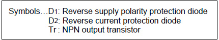
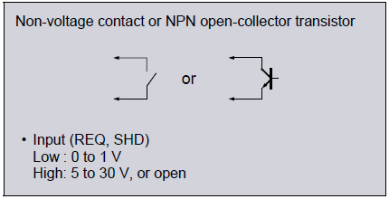
I/O Circuit and Wiring diagrams
I/O circuit diagram
|
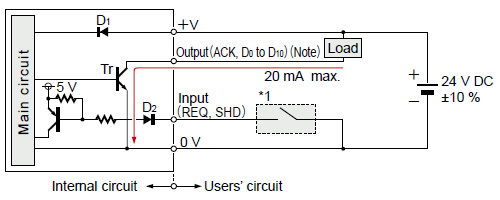
|
|
I/O Terminal Arrangement
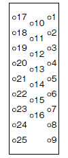 |
Attached connector |
| Pin No. | Symbol | I/O | Description |
|---|---|---|---|
| 1 | REQ | Input | Data output request |
| 2 | ACK | Output | Data being output |
| 3 | SHD | Input | Shading correction |
| 4 | - | - | Not connected |
| 5 | - | - | Not connected |
| 6 | - | - | Not connected |
| 7 | - | - | Not connected |
| 8 | G | - | 0 V |
| 9 | G | - | 0 V |
| 10 | D0 | Output | Data (20) |
| 11 | D1 | Output | Data (21) |
| 12 | D2 | Output | Data (22) |
| 13 | D3 | Output | Data (23) |
| 14 | D4 | Output | Data (24) |
| 15 | D5 | Output | Data (25) |
| 16 | D6 | Output | Data (26) |
| 17 | D7 | Output | Data (27) |
| 18 | D8 | Output | Data (28) |
| 19 | D9 | Output | Data (29) |
| 20 | D10 | Output | Data (210) |
| 21 | - | - | Not connected |
| 22 | - | - | Not connected |
| 23 | - | - | Not connected |
| 24 | G | - | 0 V |
| 25 | G | - | 0 V |
CONTACT US
If you have any questions, please select the option below to contact us or find answers.
CONTACT US
BY EMAIL
BY EMAIL
Please click your area to select country or region


Related Information
Service & Support
Requests to customers (Automation Control Components & Industrial Device) [Excluding specific product]
Requests to customers (Automation Control Components & Industrial Device) [For specific product]
Requests to customers (FA Sensors & Components [Excluding motors])
Requests to customers (Dedicated to industrial motors)
- COMPONENTS & DEVICES
- FA SENSORS & COMPONENTS
- Fiber Sensors
- Photoelectric Sensors / Laser Sensors
- Micro Photoelectric Sensors
- Light Curtains / Safety Components
- Area Sensors
- Inductive Proximity Sensors
- Particular Use Sensors
- Sensor Options
- Wire-Saving Systems
- Programmable Controllers / Interface Terminal
- Human Machine Interface
- Pressure Sensors / Flow Sensors
- Measurement Sensors
- Static Control Devices
- Laser Markers / 2D Code Readers
- Machine Vision System
- Energy Management Solutions
- Timers / Counters / FA Components
- MOTORS
![]()