
 Business
> Industrial Devices
> Automation Controls Top
> FA Sensors & Components
> Programmable Controllers / Interface Terminal
> Programmable Controllers / Interface Terminal
> Programmable Controller FP-X0
> Specifications
Business
> Industrial Devices
> Automation Controls Top
> FA Sensors & Components
> Programmable Controllers / Interface Terminal
> Programmable Controllers / Interface Terminal
> Programmable Controller FP-X0
> Specifications
Programmable Controller FP-X0
|
Specifications
Performance specifications
| Items | Specifications | |||||||
|---|---|---|---|---|---|---|---|---|
| L14R | L30R | L40R | L40MR | L60R | L60MR | |||
| Controllable I/O points | Control unit | DC input 8 points, Relay output 4 points, Transistor output 2 points |
DC input 16 points, Relay output 10 points, Transistor output 4 points |
DC input 24 points, Relay output 12 points, Transistor output 4 points |
DC input 32 points, Relay output 24 points, Transistor output 4 points |
|||
| When using FP-X E16 expansion I/O units |
- | - | 88 points max. (3 expansion units max.) |
108 points max. | ||||
| When using FP-X E30 expansion I/O units |
- | - | 130 points max. (3 expansion units max.) |
150 points max. (3 expansion units max.) |
||||
| When using FP0R expansion units |
- | - | 196 points max. (3 expansion units max.) |
216 points max. (3 expansion units max.) |
||||
| Programming method/Control method | Relay symbol/Cyclic operation | |||||||
| Program memory | Built-in Flash-ROM (Free of backup battery) | |||||||
| Program capacity | 2.5 k steps | 8 k steps | ||||||
| No of instruction |
Basic commands | Approx. 114 kinds | ||||||
| High-level commands | Approx. 230 kinds | |||||||
| Processing speed | 0.08 µs/step for basic commands 0.32 µs for high-level commands (MV commands) |
3 k steps: 0.08 µs/step for basic commands, 0.32 µs for high-level commands(MV commands) After 3 k steps: 0.58 µs/step for basic commands, 1.62 µs for high-level commands(MV commands) |
||||||
| Basic time | 0.15 ms or less |
0.18 ms or less |
0.31 to 0.35 ms or less |
0.34 to 0.39 ms or less |
||||
| I/O refreshing + basic time | When using E16: 0.4 ms × No. of units When using E30: 0.5 ms × No. of units When using FP0 expansion adapters: 1.4 ms + the refreshing time of the FP0 expansion unit |
|||||||
| Memory for processing | Relays | External input (X) (Note 1) | 960 points | 1760 points | ||||
| External output (Y) (Note 1) | 960 points | 1760 points | ||||||
| Internal relay (R) | 1008 points | 4096 points | ||||||
| Special internal relay (R) | 224 points | |||||||
| Timer・Counter (T/C) | 256 points (Note 2) | 1024 points (Note 2) |
||||||
| Timer: (1 ms, 10 ms, 100 ms, 1 s)× 32767, Counter: 1 to 32767 | ||||||||
| Link relay (L) | No | 2048 points | ||||||
| Memory area | Data register (DT) | 2500 words | 8192 words | |||||
| Special data register (DT) | 420 words | |||||||
| Link data register (LD) | No | 256 words | ||||||
| File registration (FL) | No | |||||||
| Index register (I) | 14 words (IO to ID) | |||||||
| Differential points | Equivalent to program capacity | |||||||
| Master control relay (MCR) | 32 points | 256 points | ||||||
| Label number (JP+LOOP) | 100 points | 256 points | ||||||
| No. of step programs | 128 (Engineering) | 1000 (Engineering) | ||||||
| No. of subroutines | 100 | 500 | ||||||
| No. of interrupt programs | Input: 8 programs, timing: 1 program | |||||||
| Sampling trace | No | Yes | ||||||
| Comments storage | All of the I/O comments,explanations and block comments can be saved.(Free of backup battery, 328 k bytes) |
|||||||
| PLC link function | No | Yes | ||||||
| Constant scan | In unit of 0.5 ms: 0.5 ms to 600 ms | |||||||
| Password | Available (4 or 8 digits) | |||||||
| Upload protection | Available | |||||||
| Self-diagnosis function | Checks of the watchdog timer and the program syntax | |||||||
| Program editting during Run |
Available (Capacity modified
simultaneously: 128 steps) But comments cannot be modified during the process. |
Available (Capacity modified
simultaneously: 512 steps) But comments can be modified during the process. |
||||||
| Downloading during Run | Available | |||||||
| High-speed counter (Note 3,4) |
Body input | 1-phase, 4-channel (20 kHz max.) and 2-phase, 2-channel (20 kHz max.) |
1-phase, 4-channel (50 kHz max.) and 2-phase, 2-channel (20 kHz max.) |
|||||
| Pulse output/ PWM output (Note 3,4) |
Body output | Pulse: 1-channel (20 kHz max.) PWM: 1-channel (1.6 kHz max.) |
Pulse: 2-channel (20 kHz max.) PWM: 2-channel (1.6 kHz max.) |
Pulse: 2-channel (50 kHz) PWM: 2-channel(3.0 kHz max.) |
||||
| Pulse catch input/ Interrupt program |
8 points (High-speed counting and interrupt input included) |
|||||||
| Periodical interrupt | 0.5 ms unit: 0.5 ms to 1.5 sec., 10 ms unit: 10 ms to 30 sec. | |||||||
| Analog input | No | 2-channel (For inputting any of the following items in each channel) |
||||||
| Potentiometer input Min. resistance value of potentiometer: 5 kΩ 10-bit resolution (K0 to K1000) Accuracy ± 1.0% F.S.+ accuracy of external reistors |
||||||||
| Thermistor input For inputting the resistance value of the thermistor (Min. resistance value of external thermistors + external resistance value > 2 kΩ) 10-bit resolution (K0 to K1023) Accuracy ± 1.0% F.S.+ accuracy of external thermistors |
||||||||
| Voltage input Absolute max. input voltage: 10 V 10-bit resolution (K0 to K1023) Accuracy ± 2.5% F.S.(F.S. = 10 V) |
||||||||
| Calendar/clock | No | Yes | ||||||
| Flash ROM backup (Note 5) |
Backup made according to commands of F12 and P13 |
Data memory (2500 words) |
Data memory (8192 words) |
|||||
| Automatic backup when power OFF |
Counter: 6 points (C250 to C255) Process value of the counter: 6 points (EV250 to EV255) Internal relays: 5 points (WR58 to WR62) Data memory: 300 words (DT2200 to DT2499) |
Counter: 16 points (C1008 to C1023) Process value of the counter: 16 points (EV1008 to EV1023) Internal relays: 8 points (WR248 to WR255) Data memory: 302 words (DT7890 to DT8191) |
||||||
| Backup battery | No | Yes (Backup lasting for the whole process) | ||||||
| RS485 communication port | No | Yes | No | Yes | ||||
| Notes:1) | The actual usable points depend on the combination of the hardware. |
|---|---|
| 2) | The points of the timer can be added as required. |
| 3) | The rated voltage is 24 V DC at +25 ℃+77℉. The frequency may fall according to the changes of the voltage, temperature and operating conditions. |
| 4) | The maximum frequency may vary with the difference of the operating method. |
| 5) | The allowable writing operation is within 10000 times. Areas to be held and not held can be specified using the system registers. |
General specifications
| Items | Specifications | |
|---|---|---|
| CE marking directive compliance | Low Voltage Directive, EMC Directive, RoHS Directive | |
| Operating temperature | 0 to +55℃ +32 to +131℉ | |
| Storage temperature | -40 to +70℃−40 to +158℉ | |
| Operating humidity | 10 to 95% RH (at 25℃+77℉, no condensation) |
|
| Storage humidity | 10 to 95% RH (at 25℃+77℉, no condensation) |
|
| Withstand voltage (Note 1) (Note 2) |
Input terminals ⇔ Relay output terminals |
2300 V AC, 1 minute |
| All of the transistor output terminals ⇔ All of the relay output terminals |
||
| All of the input terminals⇔ All of the power supply terminals and functional ground terminals |
||
| All of the relay output terminals ⇔ All of the power supply terminals and functional ground terminals |
||
| All of the transistor output terminals ⇔ All of the power supply terminals and functional ground terminals |
||
| Power supply terminals ⇔ Ground terminals |
1500 V AC,1 minute | |
| Input terminals ⇔ Transistor output terminals |
500 V AC,1 minute | |
| Insulation resistance (Note 1) |
Input terminals ⇔ Output terminals |
100 MΩ min. (500 V DC insulation resistance meter) |
| All of the transistor output terminals ⇔ All of the relay output terminals |
||
| All of the input terminals ⇔ All of the power supply terminals and functional ground terminals |
||
| All of the output terminals ⇔ All of the power supply terminals and functional ground terminals |
||
| Power supply terminals ⇔ Ground terminals |
||
| Vibration resistance | 5 to 8.4 Hz, 3.5 mm 0.138 inamplititude in one direction, 1 scan/1 minute 8.4 to 150 Hz,fixed acceleration of 9.8 m/s2, 1 scan/1 minute 10 minutes in X,Y,Z direction each |
|
| Shock resistance | 147 m/s2, 4 times in X, Y, Z directions each | |
| Noise immunity | 1500 V [p-p] pulse width 50 ns, 1 μs (Measured from nosie simulation method AC power supply termianls) |
|
| Operating environment | No corrosive gases or too much dust | |
| Conformed EC Directives |
EMC Directive: EN61131-2, Low Voltage Directive: EN61131-2 |
|
| Overvoltage class | II | |
| Pollution level | 2 | |
| Weight | L14R: approx. 280g L30R: approx. 450g L40R/L40MR: approx. 530g L60R/L60MR: approx. 730g |
|
Note 1) The programmable port, RS485 communication port and the internal digital circuit part are non-insulation type.
Note 2) The cut-off current is 5 mA (The default value when shipped from the factory).
Power supply specifications
· AC power supply
| Items | Specifications | |
|---|---|---|
| L14R | L30R, L40R, L40MR, L60R, L60MR | |
| Rated voltage | 100 to 240 V AC | |
| Applied voltage range | 85 to 264 V AC | |
| Inrush current | 35A max.(at 240 V AC and 25℃+77℉) | 40A max.(at 240 V AC and 25℃+77℉) |
| Momentary power off time | 10 ms (when 100 V AC used) | |
| Frequency | 50/60 Hz(47 to 63 Hz) | |
| Leakage current | 0.75 mA max.between the input and protectice ground terminals | |
| Service life of built-in power supply | 20000 h (at 55℃+131℉) | |
| Fuse | Built-in (replacement disabled) | |
| Insulation system | Transformer isolation | |
| Screw of terminal block | M3 | |
· Univeral power supply for intput (output) (L30/L40/L60 only)
| Items | Specifications |
|---|---|
| Rated output voltage | 24 V DC |
| Applied voltage range | 21.6 to 26.4 V DC |
| Rated output current | 0.3A |
| Overcurrent protection (Note) | Yes |
| Screw of terminal block | M3 |
Note) Output short protection is a temporary overcurrent protection. When the short is detected, all the power supplies of PLC will be turned OFF.
If the current load out of this specifi cation is connected and in consecutive over-loaded status, failures may occur.
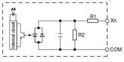
Input specifications
| Items | Specifications | ||||||
|---|---|---|---|---|---|---|---|
| L14R | L30R | L40R | L40MR | L60R | L60MR | ||
| Insulation method | Optical coupler | ||||||
| Rated input voltage | 24 V DC | ||||||
| Applied voltage range | 21.6 V DC to 26.4 V DC | ||||||
| Rated input current | Approx. 3.5 mA (Control uint: X0 to X3); Approx. 4.3 mA (Control unit: X4 and the following ones) | ||||||
| Input points per common | 8 points/COM (L14R),16 points/COM (L30R), 24 points/COM (L40R),16 points/COM×2 (L60R) (Input power supply +/- are both available.) |
||||||
| Min. ON voltage/Min. ON current | 19.2 V DC/3 mA | ||||||
| Max. OFF voltage/Max. OFF current | 2.4 V DC/1.0 mA | ||||||
| Input impedance | Approx. 6.8 kΩ (Control units: X0 to X3), Approx.5.6 kΩ (control unit X4 and the following ones) | ||||||
| Response time | OFF→ON | For X0 to X3, 1 ms max.: common input 25 µs max.(Note): When setting high-speed counter, pulse catching input and interrupt input X4 and the following ones: 1 ms max. |
For X0 to X3, 1 ms max.: common input 10 µs max.(Note): When setting high-speed counter, pulse catching input and interrupt input X4 and the following ones: 1 ms max. |
||||
| ON→OFF | Same as the above. | ||||||
| Action indicator | LED indication | ||||||
| EN61131-2 application type | TYPE 3 standard (Depending on the above-mentioned specifi cations) | ||||||
Note) The specifications mentioned above are at rated 24 V DC and operationg temperature of 25℃.
·Circuit diagram
|
Output specifications
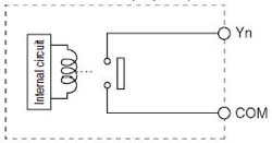
· Relay output specifictions
| Items | Specifications | ||||||
|---|---|---|---|---|---|---|---|
| L14R | L30R | L40R | L40MR | L60R | L60MR | ||
| Insulation method | Relay insulation | ||||||
| Output form | 1a output (Relay replacement disabled) | ||||||
| Rated control capacity (Resistance load) (Note) |
2A 250 V AC, 2A 30 V DC (per point) |
||||||
| Output points per common |
1 point/ COM×2 2 points/ COM×1 |
2 points/ COM×1 4 points/ COM×2 |
1 point/COM×2 2 points/COM×1 4 points/COM×2 |
4 points/COM×6 | |||
| Response time |
OFF→ON | Approx. 10 ms | |||||
| ON→OFF | Approx. 8 ms | ||||||
| Life | Mechanical | 20000000 times min.(Switching frequency 180 times/minute) | |||||
| Electrical | 100000 times min. (Depending on the rated control capacity, switching frequency of 20 times/minute) |
||||||
| Surge absorber | No | ||||||
| Action indicator | LED indication | ||||||
Note) There are restrictions on the rated current for each output block. Each usable rated current is as below.
L14:Y2 to Y5(4 points) Max. 6A in total
L30:Y4 to YD(10 points) Max. 8A in total
L40:Y4 to YFD(12 points) Max. 8A in total
L60:Y4 to YB(8 points) Max. 8A in total,YC to Y1B(16 points) Max. 8A in total
·Circuit diagram
|
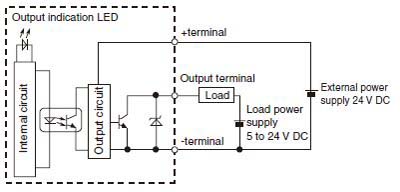
·Transistor (NPN) output specifications
| Items | Specifications | ||||||
|---|---|---|---|---|---|---|---|
| L14R | L30R | L40R | L40MR | L60R | L60MR | ||
| Insulation method | Optical coupler | ||||||
| Output method | Open-collector | ||||||
| Rated load voltage | 5 to 24 V DC | ||||||
| Allowable range of load voltage | 4.75 to 26.4 V DC | ||||||
| Max. load current | 0.5 A | ||||||
| Max. impact current | 1.5 A | ||||||
| Output points per common | 2 points/COM | 4 points/COM | |||||
| Leakage current at OFF status | 1 µA max. | ||||||
| Max. voltage drop at ON status | 0.3 V DC max. | ||||||
| Response time (at 25℃) |
OFF→ON | 10 µs max. (Load current over 15 mA) |
5 µs max. (Load current over 15 mA) |
||||
| ON→OFF | 40 µs max. (Load current over 15 mA) |
15 µs max. (Load current over 15 mA) |
|||||
| External power supply (Positive and negative teiminals) |
Voltage | 21.6 to 26.4 V DC | |||||
| Current | 15 mA max. | ||||||
| Surge absorber | Zener diode | ||||||
| Action indicator | LED indication | ||||||
·Circuit diagram
[NPN output]
[Y0 to Y3]
|
|
BY EMAIL


Requests to customers (Automation Control Components & Industrial Device) [Excluding specific product]
Requests to customers (Automation Control Components & Industrial Device) [For specific product]
Requests to customers (FA Sensors & Components [Excluding motors])
Requests to customers (Dedicated to industrial motors)
- COMPONENTS & DEVICES
- FA SENSORS & COMPONENTS
- Fiber Sensors
- Photoelectric Sensors / Laser Sensors
- Micro Photoelectric Sensors
- Light Curtains / Safety Components
- Area Sensors
- Inductive Proximity Sensors
- Particular Use Sensors
- Sensor Options
- Wire-Saving Systems
- Programmable Controllers / Interface Terminal
- Human Machine Interface
- Pressure Sensors / Flow Sensors
- Measurement Sensors
- Static Control Devices
- Laser Markers / 2D Code Readers
- Machine Vision System
- Energy Management Solutions
- Timers / Counters / FA Components
- MOTORS
![]()