FP2SH (Discontinued Products)
We are sorry, the products have been discontinued. Please refer to the details of the discontinued products and the recommended substitutes list below.
 |
September 30, 2022 |
|
|
Cautions For Use
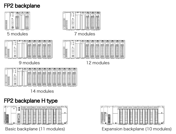
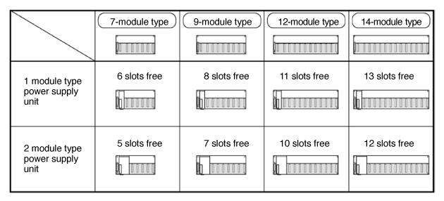
Basic Configurations by number of slots
The building block scheme allows you to combine units as desired.
Five types of backplanes and Two types of backplanes H types are available for the FP2/FP2SH. A variety of input/output units can be installed as desired on the backplane.
Although most of the I/O units and intelligent units can be combined freely in the layout,you should check the following three points when selecting your units:
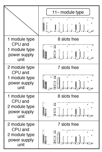
2-module units
A2 modules type power supply unit and 2 modules type CPU are available.
| Type |
Part number |
| 100 to 240V AC type power supply unit |
FP2-PSA3 |
| 24V DC type power supply unit |
FP2-PSD2 |
| CPU with 64-point input |
FP2-C1D |
| CPU with S-LINK |
FP2-C1SL |
Mounting
The number of units that can be installed is determined by the number of modules of the backplane used, the power supply unit to be installed, and the CPU.
| 1 module type CPU |
Standard type CPU |
| 2 modules type CPU |
CPU with 64-point input, CPU with S-LINK |
| 1 module type power supply unit |
100V 2.5A, 200V 2.5A |
| 2 modules type power supply unit |
100 to 240V 5A, 24V DC 5A |
CPU backplane
FP2 backplane
 |
| * slots free: Number of slots where units can be installed |
|
FP2 backplane H type
A maximum of eight I/O units (including the unit built in the CPU) can be controlled per backplane. Even if further I/O units are installed, they are not recognized.
| Note) | When using the CPU unit with S-LINK, seven slots are free, however, the units actually usable are only six. (Refer to Chapter 3 I/O Allocation.) |
|---|
Expansion of Backplane
FP2 backplane
Only one backplane can be added-on for expansion.
Expansion is simply connecting a new backplane with a special expansion cable. Any backplane other than a 5-module type can be used for expansion.
Notes
- A 5-module type backplane cannot be expanded.
- A 5-module type backplane cannot be added on for expansion.
- Only one backplane can be added-on for expansion.
- A power supply unit is also necessary on an expansion backplane.
- Do not install a CPU on an expansion backplane.
- There is no need to make the number of modules on the expansion backplane equal to the number of modules on the CPU backplane.
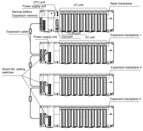
FP2 backplane H type
The basic FP2 backplane H type that the CPU unit can be installed and the expansion
backplane H type that only the I/O units and the intelligent I/O units can be installed are
available.
A maximum of eight I/O units (including the unit built in the CPU) can be controlled per
backplane. Even if further I/O units are installed, they are not recognized.
Up to three expansion backplanes can be added on for expansion.
Use the board No. setting switches on the board to distinguish the expansion backplane.
A power supply unit is also necessary on an expansion backplane.
Mounting
The number of units that can be installed is determined by the number of modules of the backplane used and the power supply unit to be installed.
FP2 backplane
 |
| * slots free: Number of slots where units can be installed |
|
FP2 backplane H type
| Note) | When using the CPU unit with S-LINK, seven slots are free, however, the units actually usable are only six. (Refer to Chapter 3 I/O Allocation.) |
|---|
Expansion cable
| Order number |
Length |
Ferrite core |
| FP2-EC |
60 cm |
1 |
| FP2-EC2 |
2 m |
2 |
| Note) | With the backplalne H type, the total cable length can be arranged within 3.2 m. |
|---|
Restrictions on Unit Types
| Backplanes and units used |
System configuration |
| CPU backplane |
Expansion backplane |
Slave station
system backplane |
| Install in order from the left to the right, the power supply unit, the CPU unit, the I/O and the intelligent units. |
Install in order from the left to the right, the power supply unit, the I/O and the intelligent units. |
Master backplane for slave station
system |
Expansion backplane for slave
station system |
 |
 |
Install in order from the left to the right,
the power supply unit, the Remote I/O
slave unit,the I/O and the intelligent
units.*Replace the CPU on the CPU
backplane with a remote I/O slave unit. |
Install in order from the left to the right,
the power supply unit, the I/O and the
intelligent units.* Same as the installation
of the expansion backplane. |
| Backplane |
(5-module type) |
Available |
Not available |
Available |
Available |
| (7-, 9-, 12-, 14- module typs) |
Available |
Available |
Available |
Available |
| Backplane H type |
Basic (11-module type) |
Available |
Not available |
Available |
Available |
| Expansion (10-module type) |
Not available |
Available*4 |
Not available |
Available |
| Power supply unit |
Available |
Available |
Available |
Available |
| CPU unit |
Available |
Not available |
Not available |
Not available |
| Remote I/O slave unit |
Not available |
Not available |
Available |
Not available |
| Input unit |
Available |
Available |
Available |
Available |
| Output unit |
Available |
Available |
Available |
Available |
| I/O mixed unit |
Available |
Available |
Available |
Available |
| Analog input unit |
Available |
Available |
Not available |
Not available |
| Analog output unit |
Available |
Available |
Not available |
Not available |
| High-speed counter unit |
Availablenote 1) |
Availablenote 1) note 5) |
Availablenote 6) |
Availablenote 6) |
| Pulse I/O unit |
Availablenote 1) |
Availablenote 1) note 5) |
Availablenote 6) |
Availablenote 6) |
| Positioning unit |
Available |
Available |
Availablenote 7) |
Availablenote 7) |
| Positioning unit RTEX |
Available |
Available |
Availablenote 7) |
Availablenote 7) |
| Positioning unit Interpolation type |
Available |
Available |
Availablenote 7) |
Availablenote 7) |
| Serial data unit |
Available |
Available |
Available |
Available |
| Computer communication unit |
Availablenote 2) |
Not available |
Not available |
Not available |
| S-LINK unit |
Available |
Available |
Not available |
Not available |
| Multi-wire link unit |
MEWNET-F mode |
Availablenote 3) |
Availablenote 3) |
Not available |
Not available |
| MEWNET-W mode |
Availablenote 2) |
Not available |
Not available |
Not available |
| MEWNET-W2 mode |
Availablenote 2) |
Not available |
Not available |
Not available |
| ET-LAN2 unit |
Availablenote 2) |
Not available |
Not available |
Not available |
| Multi Communication Unit |
Availablenote 2) |
Availablenote 2) |
Not available |
Not available |
| MEWNET-VE2 Link Unit |
Availablenote 2) |
Not available |
Not available |
Not available |
| FNS unit |
Available |
Available |
Not available |
Not available |
| FMU unit |
Available |
Available |
Not available |
Not available |
| *1 |
When "Mode B: Unit with interrupt function" has been specified,
the unit will be treated as interrupt unit, and 8 interrupts
per unit will be available for use. However, when "Mode B" has
been set for the unit, 2 units can be used with 1 CPU unit.
When "Mode C: Intelligent unit that generate interrupts" has
been specified, and 1 interrupt per unit will be available for
use. However, when "Mode C" has been set for the unit, 8
units can be used with 1 CPU unit. |
| *2 | Check the limitations on combining link units given below. |
|---|
| *3 | In the MEWNET-F mode, up to four units counting the CPU and expansion sides. |
|---|
| *4 | With the backplane H type, the total expansion cable length can be arranged within 3.2 m. |
|---|
| *5 | The unit cannot be installed on the 32th slot (last slot) when using the H-type backplane. |
|---|
| *6 | The interrupt function is not available for the backplane on the slave station system. |
|---|
| *7 | With the backplane on the slave station system, the time taken from the startup until the completion of positioning should be longer than a scan time. |
|---|
Limitations on Combining Link Units
| Unit type and mode |
When CPU unit is FP2 |
When CPU unit is FP2SH |
| Computer communication unit |
Only 1 unit * |
Can be installed within 3 units in combination with W link, CCU and MCU (PC link mode). |
| Multi-wire Link unit (MEWNET-W mode) |
Can be installed within 5 units in combination with W link, CCU and MCU (PC link mode). |
| Can be installed within 2 units in combination with MCU in PC (PLC) link mode. |
| Multi-wire Link unit (MEWNET-W2 mode)ET-LAN unit |
Up to 3 units.
Up to 2 units when a PLC link is included. |
Up to 8 units.
Up to 2 units when a PLC link is included. |
| Multi Communication Unit (PC(PLC) link mode) |
Up to 3 units can be used. Up to 2 units out of 3, when including PC (PLC) link. |
Up to 8 units can be used. Up to 2 units out of 8, when including PC (PLC) link. |
| Can be installed within 5 units in combination with W link, CCU and MCU. |
| Canbe installed within 2 units in combination withWlink unit in PC(PLC) link mode. |
| Multi Communication Unit (Computer link mode) |
Up to 8 units can be used. |
| MEWNET-VE2 Link Unit |
Not available |
Can be installed within 2 units in combination with Multi Communication Unit. |
| * | Depending on the location of the connected boards and the commands used for communication, up to 3 units can be used. For more details, refer to the limitations on communication given on the next page and the Computer Communication Unit Manual. |
|---|
Limitations on Current Consumption
| Product number |
Part number |
Rated current (5 V) |
| FP2-PSA1 |
AFP2631 |
2.5 A |
| FP2-PSA2 |
AFP2632 |
2.5 A |
| FP2-PSA3 |
AFP2633 |
5 A |
| FP2-PSD2 |
AFP2644 |
5 A |
Internal and External Power Supplies
Internal power supply (5 V DC)
5 V power supply used for driving the internal circuit of each unit is supplied from the power supply unit through the internal bus of the backplane.
External power supply (24 V DC)
- 24 V power supply used as the input power supply of input units and the output circuit driving power of output units is supplied from the external terminal.
For 24 V power supply, a commercial power supply unit is used.
Combining Units and Selecting a Backplane
The power consumed by each unit is shown in the next page. Give consideration to the combination of units so that the rated capacity of the 5 V and 24 V power supplies should not exceeded.
Examples of current consumption calculation
The table below shows the combinations of a 8-slot backplane and typical units.
| Item |
Quantity |
5 V current consumption (mA) |
24 V current consumption (mA) |
| CPU unit (FP2-C1) |
1 |
410 |
0 |
| Master backplane (FP2-BP09) |
1 |
60 |
0 |
| Input unit (FP2-X16D2) |
3 |
60x3=180 |
8x16x3=384 |
| Output unit (FP2-Y16R) |
4 |
120x4=480 |
160x4=640 |
| Total current consumption |
|
1130 |
1024 |
Table of Current Consumption (5 V power supply)
| Item |
Product number |
Part number |
5 V power consumption (mA) |
| FP2SH CPU unit |
FP2-C2 |
AFP2231 |
750mA or less |
| FP2-C2P |
AFP2235 |
750mA or less |
| FP2-C3P |
AFP2255 |
750mA or less |
| Backplane |
FP2-BP05 |
AFP25005 |
5mA or less |
| FP2-BP07 |
AFP25007 |
60mA or less |
| FP2-BP09 |
AFP25009 |
60mA or less |
| FP2-BP12 |
AFP25012 |
60mA or less |
| FP2-BP14 |
AFP25014 |
60mA or less |
| Backplane H type |
FP2-BP11MH |
AFP25011MH |
60mA or less |
| FP2-BP10EH |
AFP25010EH |
60mA or less |
| Input unit |
DC input |
16-point terminal block, 12 V to 24 V DC |
FP2-X16D2 |
AFP23023 |
60mA or less |
| 32-point connector, 24 V DC |
FP2-X32D2 |
AFP23064 |
80mA or less |
| 64-point connector, 24 V DC |
FP2-X64D2 |
AFP23067 |
100mA or less |
| Output unit |
Relay output |
6-point terminal block |
FP2-Y6R |
AFP23101 |
50mA or less |
| 16-point terminal block |
FP2-Y16R |
AFP23103 |
120mA or less |
| Transistor output |
16-point terminal block, NPN |
FP2-Y16T |
AFP23403 |
100mA or less |
| 32-point connector, NPN |
FP2-Y32T |
AFP23404 |
130mA or less |
| 64-point connector, NPN |
FP2-Y64T |
AFP23407 |
210mA or less |
| 16-point terminal block, PNP |
FP2-Y16P |
AFP23503 |
80mA or less |
| 32-point connector, PNP |
FP2-Y32P |
AFP23504 |
130mA or less |
| 64-point connector, PNP |
FP2-Y64P |
AFP23507 |
210mA or less |
| I/O mixed unit |
32-point 24 V DC input/32-point connector, NPN output type |
FP2-XY64D2T FP2-XY64D7T |
AFP23467 AFP23477 |
160mA or less |
| 32-point 24 V DC input/32-point connector, PNP output type |
FP2-XY64D2P FP2-XY64D7P |
AFP23567 AFP23577 |
160mA or less |
| Intelligent unit |
Analog input unit (Voltage/current type) |
FP2-AD8VI |
AFP2400L |
400mA or less |
| Analog input unit (Channel type) |
FP2-AD8VI |
AFP2401 |
300mA or less |
| RTD input unit |
FP2-RTD |
AFP2402 |
300mA or less |
| Analog output unit |
FP2-DA4 |
AFP2410 |
600mA or less |
| High-speed counter unit |
NPN output |
FP2-HSCT |
AFP2441 |
450mA or less |
| PNP output |
FP2-HSCP |
AFP2451 |
450mA or less |
| Pulse I/O unit |
NPN output |
FP2-PXYT |
AFP2442 |
500mA or less |
| PNP output |
FP2-PXYP |
AFP2452 |
500mA or less |
| Positioning unit |
2-axis type |
FP2-PP2 |
AFP2432
AFP2434 |
225mA or less |
| 4-axis type |
FP2-PP4 |
AFP2433
AFP2435 |
400mA or less |
| Positioning unit (Multifunction type) |
2-axis type |
Transistor output type |
FP2-PP21 |
AFP2432 |
200mA or less |
| Line driver output type |
FP2-PP22 |
AFP2434 |
200mA or less |
| 4-axis type |
Transistor output type |
FP2-PP41 |
AFP2433 |
350mA or less |
| Line driver output type |
FP2-PP42 |
AFP2435 |
350mA or less |
| Positioning unit RTEX |
2-axis type |
FP2-PN2AN |
AFP243610 |
300mA or less |
| 4-axis type |
FP2-PN4AN |
AFP243620 |
300mA or less |
| 8-axis type |
FP2-PN8AN |
AFP243630 |
300mA or less |
| Positioning unit (Interpolation type) |
2-axis type |
Transistor output type |
FP2-PP2T |
AFP243710 |
300mA or less |
| Line driver output type |
FP2-PP2L |
AFP243711 |
300mA or less |
| 4-axis type |
Transistor output type |
FP2-PP4T |
AFP243720 |
300mA or less |
| Line driver output type |
FP2-PP4L |
AFP243721 |
300mA or less |
| Serial data unit |
FP2-SDU |
AFP2460 |
60mA or less |
Multi communication unit
with Communication block (1-unit or 2-unit)
* Soon, a sales schedule |
FP2-MCU |
AFP2465 |
480mA or less |
| Computer communication unit (C.C.U.) |
FP2-CCU |
AFP2462 |
60mA or less |
| S-LINK unit |
128 points, 1 ch |
FP2-SL2 |
AFP2780 |
130mA or less |
| Multi-wire link unit |
FP2-MW |
AFP2720 |
220mA or less |
| ET-LAN2 unit |
FP2-ET1 |
AFP27901 |
670mA or less |
Table of Current Consumption (24 V power supply)
| Item |
Product number |
Part number |
24 V power consumpion (mA) |
| Input unit |
DC input |
16-point terminal block, 12 V to 24 V DC |
FP2-X16D2 |
AFP23023 |
8 mA or less/point |
| 32-point connector, 24 V DC |
FP2-X32D2 |
AFP23064 |
4.3 mA or less/point |
| 64-point connector, 24 V DC |
FP2-X64D2 |
AFP23067 |
4.3 mA or less/point |
| Output unit |
Relay output |
6-point terminal block |
FP2-Y6R |
AFP23101 |
70mA or less |
| 16-point terminal block |
FP2-Y16R |
AFP23103 |
160mA or less |
| Transistor output |
16-point terminal block, NPN |
FP2-Y16T |
AFP23403 |
120mA or less |
| 32-point connector, NPN |
FP2-Y32T |
AFP23404 |
140mA or less |
| 64-point connector, NPN |
FP2-Y64T |
AFP23407 |
250mA or less |
| 16-point terminal block, PNP |
FP2-Y16P |
AFP23503 |
70mA or less |
| 32-point connector, PNP |
FP2-Y32P |
AFP23504 |
150mA or less |
| 64-point connector, PNP |
FP2-Y64P |
AFP23507 |
270mA or less |
| I/O mixed unit |
32-point 24 V DC input / 32-point connector, NPN output type |
FP2-XY64D2T FP2-XY64D7T |
AFP23467 AFP23477 |
Input :4.3 mA or less/point |
| Output : 120 mA or less |
| 32-point 24 V DC input / 32-point connector, PNP output type |
FP2-XY64D2P FP2-XY64D7P |
AFP23567 AFP23577 |
Input : 4.3 mA or less/point |
| Output :130 mA or less |
| *1 | The input unit displays the current flowing to the internal circuit. The other units display the current value required to drive the internal circuit.
This value dose not include the load current of the output unit. |
|---|
| *2 | Refer to the manual of the each unit you are using to confirm the current consumed at 24 V by S-LINK related unit and the positioning unit. |
|---|
Return to top
Return to top

 Business
> Industrial Devices
> Automation Controls Top
> FA Sensors & Components
> Programmable Controllers / Interface Terminal
> Programmable Controllers / Interface Terminal
> FP2SH(Discontinued Products)
> Cautions For Use
Business
> Industrial Devices
> Automation Controls Top
> FA Sensors & Components
> Programmable Controllers / Interface Terminal
> Programmable Controllers / Interface Terminal
> FP2SH(Discontinued Products)
> Cautions For Use