
 Business
> Industrial Devices
> Automation Controls Top
> FA Sensors & Components
> Pressure Sensors / Flow Sensors
> Pressure Sensors / Flow Sensors
> Head-separated Dual Display Digital Pressure Sensor [For Gas] DPH-100 / DPC-100
> Cautions For Use
Business
> Industrial Devices
> Automation Controls Top
> FA Sensors & Components
> Pressure Sensors / Flow Sensors
> Pressure Sensors / Flow Sensors
> Head-separated Dual Display Digital Pressure Sensor [For Gas] DPH-100 / DPC-100
> Cautions For Use
Head-separated Dual Display Digital Pressure Sensor [For Gas] DPH-100 / DPC-100
Cautions For Use
- Never use this product as a sensing device for personnel protection.
- In case of using sensing devices for personnel protection, use products which meet laws and standards, such as OSHA, ANSI or IEC etc., for personnel protection applicable in each region or country.
- The DPH-100 series is designed for use with air and non-corrosive gas. It cannot be used with liquid or corrosive and inflammable gases.
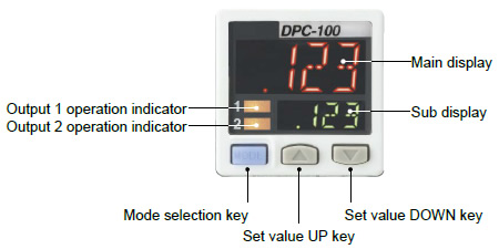
Part description
|
Wiring
- Make sure that the power supply is off while wiring.
- Verify that the supply voltage variation is within the rating.
- If power is supplied from a commercial switching regulator, ensure that the frame ground (F.G.) terminal of the power supply is connected to an actual ground.
- In case noise generating equipment (switching regulator, inverter motor, etc.) is used in the vicinity of this sensor, connect the frame ground (F.G.) terminal of the equipment to an actual ground.
- Do not run the wires together with high-voltage lines or power lines or put them in the same raceway. This can cause malfunction due to induction.
- Incorrect wiring will cause problems with operation.
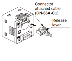
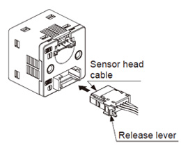
Connection
- Do not apply stress directly to the connection cable leader or to the connector.
 |
 |
|
<Connector of connector attached cable> |
<Connector of sensor head cable> |
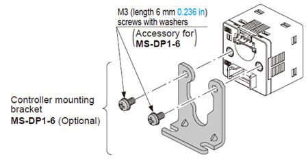
Mounting
- When tightening the controller to the controller mounting bracket MS-DP1-6 (optional), use a tightening torque of 0.5 N·m or less.
|
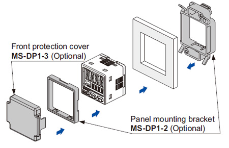
- The MS-DP1-2 panel mounting bracket (optional) and the MS-DP1-3 front protection cover (optional) are also available.
|
Piping
・ |
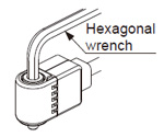
Use a hexagonal wrench to install sensor head. For the tightening torque, refer to the following diagram. If excessive tightening torque is applied, the pressure port of the sensor head or the M5 male screw of the commercial coupling will get damaged. In case of R1/8 male thread type, wrap sealing tape around the coupler when connecting to prevent leakage. |
 |
| Pressure port | Hexagonal wrench (bolt width) | Tightening torque |
|---|---|---|
| R1/8 male thread | 5 mm 0.197 in | 9.8 N·m or less |
| M3 male thread | 3 mm 0.118 in | 0.8 N·m or less |
| M5 male thread | 1.5 N·m or less |
Others
- Use within the rated pressure range.
- Do not apply pressure exceeding the pressure withstandability value. The diaphragm will get damaged and correct operation shall not be maintained.
- Do not use during the initial transient time (controller: 0.5 sec. approx, sensor head: 50 ms approx.) after the power supply is switched on.
- Avoid dust, dirt, and steam.
- Take care that the sensor does not come in direct contact with water, oil, grease, or organic solvents, such as, thinner, etc.
- Do not insert wires, etc., into the pressure port. The diaphragm will get damaged and correct operation shall not be maintained.
- Do not operate the keys with pointed or sharp objects.
RUN mode
- This is the normal operating mode.
| Setting item | Description |
|---|---|
| Threshold value setting | The threshold values for ON / OFF operation can be changed directly by pressing the increment key (UP) and the decrement key (DOWN). |
| Zero-adjustment function | This forces the pressure value display to be reset to zero when the pressure port is open on the atmospheric pressure side. |
| Key lock function | Stops key operations from being accepted. |
| Peak hold / bottom hold function | Displays the peak value and bottom value for fluctuating pressure. The peak value appears in the main display, and the bottom value appears in the sub display. |
MENU SETTING mode
- If the mode selection key is pressed and held for 2 sec. in RUN mode, the mode will switch to MENU SETTING mode.
- If the mode selection key is pressed while a setting is being made, the mode will switch to RUN mode. In this case, the settings that have been changed will be entered.
| Setting item | Description |
|---|---|
| Comparative output 1 output mode setting |
Sets the output mode for comparative output 1. |
| Comparative output 2 output mode setting |
Sets the output mode for comparative output 2. |
| Analog voltage / current output selection |
Selects analog voltage output or analog current output. |
| External input selection | Selects auto-reference function, or remote zero-adjustment function. |
| NO / NC selection | Normally open (NO) or normally closed (NC) can be selected. |
| Response time setting | Sets the response time. The response time can be selected from 0.5 ms, 1 ms, 2.5 ms, 5 ms, 10 ms, 25 ms, 50 ms, 100 ms, 250 ms, 500 ms, 1,000 ms and 5,000 ms. |
| Display color switching for main display | Allows the color for the main display to be changed. The colors can be set to “red / green” or “green / red” to correspond to ON / OFF output, or it can be fixed at “red” or “green” all the time. |
| Unit switching | Pressure unit can be changed. |
PRO mode
- If the mode selection key is pressed and held for 5 sec. in RUN mode, the mode will switch to PRO mode.
- If the mode selection key is pressed while a setting is being made, the mode will switch to RUN mode. In this case, the settings that have been changed will be entered.
| Setting item | Description |
|---|---|
| Sub display switching | Changes the information in the sub display during RUN mode operation to the current pressure unit, number and desired alphanumeric display. |
| Display refresh rate switching | Changes the display refresh rate for the pressure value displayed in the main display. |
| Hysteresis fix value switching | Sets the hysteresis for EASY mode and window comparator mode. (8 steps) |
| Linked display color switching | Allows the display color for the main display to be switched in line with the output operation for comparative output 1 or comparative output 2. |
| External input relation selection | The setting contents set at the external input selection in MENU SETTING mode can be shifted to correspond to either comparative output 1, 2 or 1 / 2. |
| ECO mode setting | Allows power consumption to be reduced by dimming the display or turning it off. |
| Setting check code | Allows the setting details to be checked via codes. (Refer to below) |
| Setting copy mode | Allows the setting details for the master controller to be copied to slave controllers. |
| Reset setting | Resets the settings to the factory settings. |
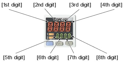
| Table of codes |
| |||||||||||||||||||||||||||||||||||||||||||||||||||||||||||||||||||||||||||||||||||||||
| |||||||||||||||||||||||||||||||||||||||||||||||||||||||||||||||||||||||||||||||||||||||
| |||||||||||||||||||||||||||||||||||||||||||||||||||||||||||||||||||||||||||||||||||||||
| Note: | When positive pressure type of the pressure sensor head is connected to the controller for use inside Japan, “0” (MPa) or “1” (kPa) is displayed. When compound pressure type or vacuum pressure type is connected, only “1” (kPa) is displayed. |
|---|
BY EMAIL


Requests to customers (Automation Control Components & Industrial Device) [Excluding specific product]
Requests to customers (Automation Control Components & Industrial Device) [For specific product]
Requests to customers (FA Sensors & Components [Excluding motors])
Requests to customers (Dedicated to industrial motors)
- COMPONENTS & DEVICES
- FA SENSORS & COMPONENTS
- Fiber Sensors
- Photoelectric Sensors / Laser Sensors
- Micro Photoelectric Sensors
- Light Curtains / Safety Components
- Area Sensors
- Inductive Proximity Sensors
- Particular Use Sensors
- Sensor Options
- Wire-Saving Systems
- Programmable Controllers / Interface Terminal
- Human Machine Interface
- Pressure Sensors / Flow Sensors
- Measurement Sensors
- Static Control Devices
- Laser Markers / 2D Code Readers
- Machine Vision System
- Energy Management Solutions
- Timers / Counters / FA Components
- MOTORS
![]()