40 mm Beam Pitch General Purpose Area Sensor NA40 (Discontinued Products)
We are sorry, the products have been discontinued. Please refer to the details of the discontinued products and the recommended substitutes list below.
 |
September 29, 2023 |
|
|
Cautions For Use
- Never use this product as a sensing device for personnel protection.
- For sensing devices to be used as safety devices for press machines or forpersonnel protection, use products which meet standards, such as OSHA, ANSI or IEC etc., for personnel protection applicable in each region or country.
- If this product is used as a sensing device for personnel protection, death or serious body injury could result.
- For a product which meets safety standards, use the safety light curtains.
Setting of interference prevention function
| ・ |
Make sure that the power supply is off while operating the frequency selection switch. If the switch is operated while the power is on, the sensor may go into the operation stopped state. However, to restart the sensor, turn the power off and on again. |
| ・ |
The frequency selection switch should not be set to the positions other than those specified below. |
| ・ |
When the sensor A breaks down due to any reason, the sensor B goes into the operation stopped state. In order to check the operation of the sensor B, set the frequency selection switch to "1". Note that when only the sensor B breaks down, the sensor A keeps operation correctly. |
- When the interference prevention function is not used (when one set of sensor is used) make sure that the frequency selection switch in both the emitter and receiver is set to "1". If the switch is set to other than that, the sensor may not operate properly.
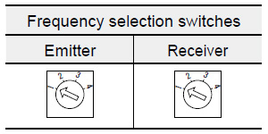
| When using one set of sensor |
|
|
Set the switches of both the emitter and the receiver at "1".
The sensor does not function normally at other settings. |
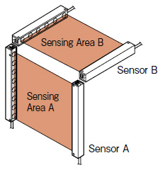
| When using two sets of sensor |
- Up to two sets of sensors can be mounted close together by using the interference prevention function. Set the interference prevention function in the following procedure.
|
|
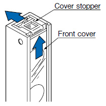
| (1) |
Set the frequency selection switch. Firstly, push up the front cover while pressing the cover stopper towards the arrow shown in the right figure. |
| (2) |
Turn the frequency selection switch with the accessory adjusting screwdriver to select the frequency. |
|
|
|
|
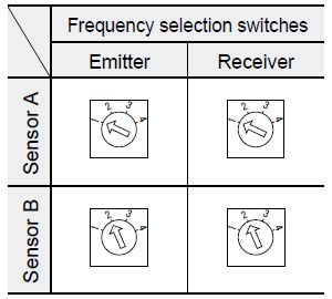
Set the switches of both the emitter and the receiver of Sensor A at "1", and both
switches of Sensor B at "2".
The sensors do not function normally at other settings. |
| (3) |
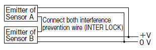
Connect the interference prevention wire (INTER LOCK) of Sensor A and B. |
|
|
- Connect both the 0 V wires in common.
- +V wires need not be connected in common.
|
| Note: |
Total of wire length between Sensor A and B is 20 m 65.617 ft max.
(Total of wire length of interference prevention wire and 0 V is 20 m 65.617 ft max.) |
Return to top
Return to top

 Business
> Industrial Devices
> Automation Controls Top
> FA Sensors & Components
> Sensors
> Area Sensors
> 40 mm Beam Pitch General Purpose Area Sensor NA40(Discontinued Products)
> Cautions For Use
Business
> Industrial Devices
> Automation Controls Top
> FA Sensors & Components
> Sensors
> Area Sensors
> 40 mm Beam Pitch General Purpose Area Sensor NA40(Discontinued Products)
> Cautions For Use