Universal Sensor Mounting Stand MS-AJ
Dimensions
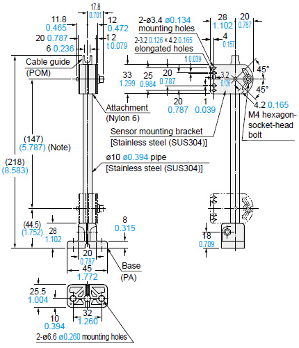
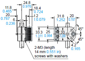
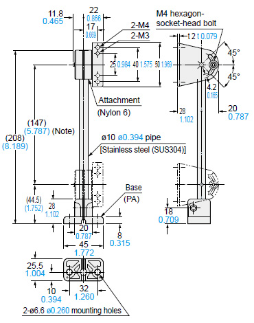
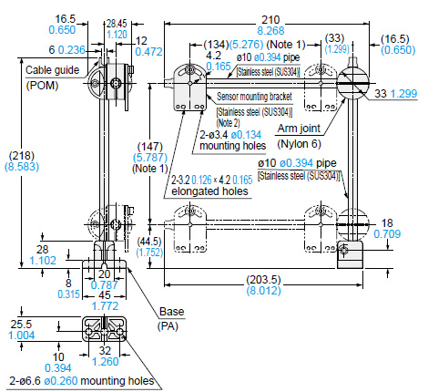
MS-AJ1
Basic assembly |
 |
Two M3 (length 14 mm 0.551 in) screws with washers, two M3 (length 16 mm 0.630 in) screws with washers, two M3 (length 18 mm 0.709 in) screws with washers, one auxiliary mounting plate for EQ-20 series and one auxiliary mounting plate for EX-40 series are attached.
Note:
The dimensions in the brackets indicate the adjustable range of the movable part. |
|
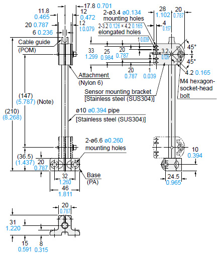
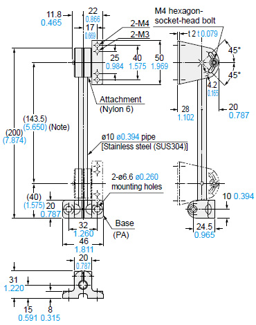
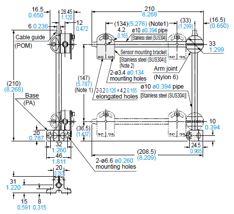
MS-AJ2
Basic assembly |
 |
Two M3 (length 14 mm 0.551 in) screws with washers, two M3 (length 16 mm 0.630 in) screws with washers, two M3 (length 18 mm 0.709 in) screws with washers, one auxiliary mounting plate for EQ-20 series and one auxiliary mounting plate for EX-40 series are attached
Note:
The dimensions in the brackets indicate the adjustable range of the movable part. |
|
MS-AJ1 MS-AJ2
Basic assembly
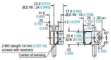
Assembly dimensions with CX-400/440 series,LS-400 series, EZ-10 series
(Mounting part only) |
 |
|
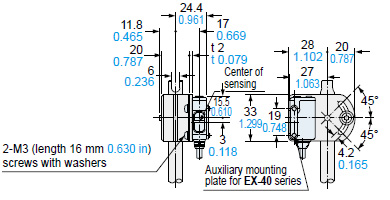
Assembly dimensions with EX-40 series
(Mounting part only) |
 |
|
Assembly dimensions with RF-210 (Reflector)
(Mounting part only) |
 |
|
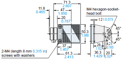
MS-AJ1-M
Assembly for reflector |
 |
Two M3 (length 8 mm 0.315 in) screws with washers and two M4 (length 8 mm 0.315 in) screws with washers are attached.
Note:
The dimensions in the brackets indicate the adjustable range of the movable part. |
|
MS-AJ2-M
Assembly for reflector |
 |
Two M3 (length 8 mm 0.315 in) screws with washers and two M4 (length 8 mm 0.315 in) screws with washers are attached.
Note:
The dimensions in the brackets indicate the adjustable range of the movable part. |
|
MS-AJ1-M MS-AJ2-M
Assembly for reflector
Assembly dimensions with RF-220 (Reflector)
(Mounting part only) |
 |
|
Assembly dimensions with RF-230 (Reflector)
(Mounting part only) |
 |
|
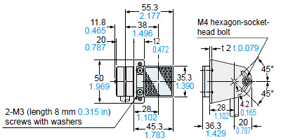
MS-AJ1-A
Lateral arm assembly |
 |
Two M3 (length 14 mm 0.551 in) screws with washers, two M3 (length 16 mm 0.630 in) screws with washers, two M3 (length 18 mm 0.709 in) screws with washers, one auxiliary mounting plate for EQ-20 series and one auxiliary mounting plate for EX-40 series are attached.
Notes:
1) The dimensions in the brackets indicate the adjustable range of the movable part.
2) Refer to MS-AJ1/MS-AJ2 (basic assembly) for the assembly diagram with the sensor mounting bracket, sensor or reflector. |
|
MS-AJ2-A
Lateral arm assembly |
 |
Two M3 (length 14 mm 0.551 in) screws with washers, two M3 (length 16 mm 0.630 in) screws with washers, two M3 (length 18 mm 0.709 in) screws with washers, one auxiliary mounting plate for EQ-20 series and one auxiliary mounting plate for EX-40 series are attached.
Notes:
1) The dimensions in the brackets indicate the adjustable range of the movable part.
2) Refer to MS-AJ1/MS-AJ2 (basic assembly) for the assembly diagram with the sensor mounting bracket, sensor or reflector. |
|
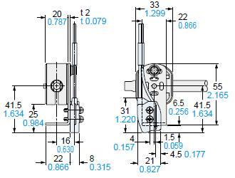
MS-AJ1-F
Assembly for fiber |
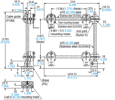 |
Note:
1) The dimensions in the brackets indicate the adjustable range of the movable part. |
|
MS-AJ2-F
Assembly for fiber |
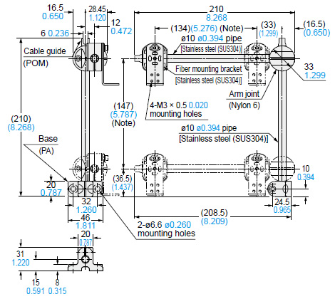 |
Notes:
1) The dimensions in the brackets indicate the adjustable range of the movable part. |
|
MS-AJ1-F MS-AJ2-F
Assembly for fiber
Fiber mounting bracket / MS-FD-1 |
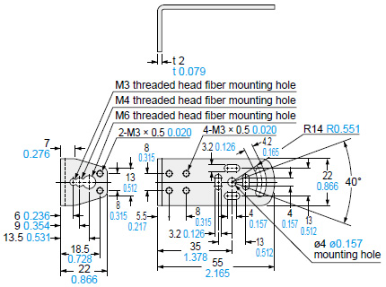 |
Material:
Stainless steel (SUS304) |
|
Assembly dimensions with FD-L51
(Mounting part only) |
 |
|
Assembly dimensions with FD-FM2
(Mounting part only) |
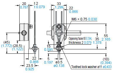 |
Note:
The above diagram is in case of M6 threaded head fiber. |
|
Return to top
Return to top

 Business
> Industrial Devices
> Automation Controls Top
> FA Sensors & Components
> Sensors
> Sensor Options
> Universal Sensor Mounting Stand MS-AJ
> Dimensions
Business
> Industrial Devices
> Automation Controls Top
> FA Sensors & Components
> Sensors
> Sensor Options
> Universal Sensor Mounting Stand MS-AJ
> Dimensions


