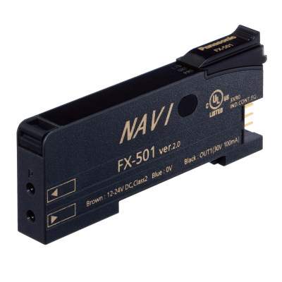
Basic Information
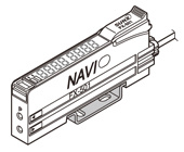
At the industry’s leading edge


UL : Approved Listing
* There is no change in Model No. and price due to version upgrade.
* Cover opened state is shown.
Features
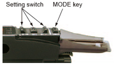
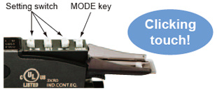
Improved the operability and visibility of the operation keys
Operation keys (setting switch and MODE key) have been renewed to be easy to operate. Also, the color of the keys has been changed from black to light gray to achieve good visibility in dim light.
[Previous]

[Upgraded (Ver. 2)]
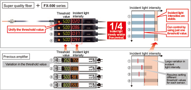
High stability!
When the FX-500 series is used together with our super quality fiber, the incident light intensity variation among units is decreased to only 1/4 of that of conventional models.
By being close to absolute values instead of modified digital values, changes in detection that could not be found in the past can now be monitored.
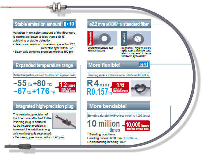
A quality that surpassed that of standard fibers!
New fibers developed using a new manufacturing method adopted by our own factory along with a persistent quality control system.
The basic performance of a standard fiber is greatly enhanced!
Max. 25 μs response time
FX-500 with its high response time contributes to improve productivity.
Performing minute object detection when using a small diameter fiber is now possible with a high response time and longer sensing range.
HYPR(Hyper) mode incorporated
FX-500 in combination with small diameter fibers which can handle challenging detections, allows long sensing range.
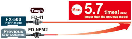
Note: When using FD-NFM2.
So accurate! Sharp detection with suppressed hysteresis
FX-500 with its accurate detection catches fractional differences in light intensity, achieving high precision and solving low-hysteresis applications.
Long range detection of small objects with small difference in light intensity [H-02 mode]
![Long range detection of small objects with small difference in light intensity [H-02 mode]](https://ap.industry.panasonic.com/hubfs/pid-corp/products/fasys/sensor/fiber/fx-500/images/pic09.jpg)
Highly accurate detection while avoiding saturation [H-01 mode]
![Highly accurate detection while avoiding saturation [H-01 mode]](https://ap.industry.panasonic.com/hubfs/pid-corp/products/fasys/sensor/fiber/fx-500/images/pic10.jpg)
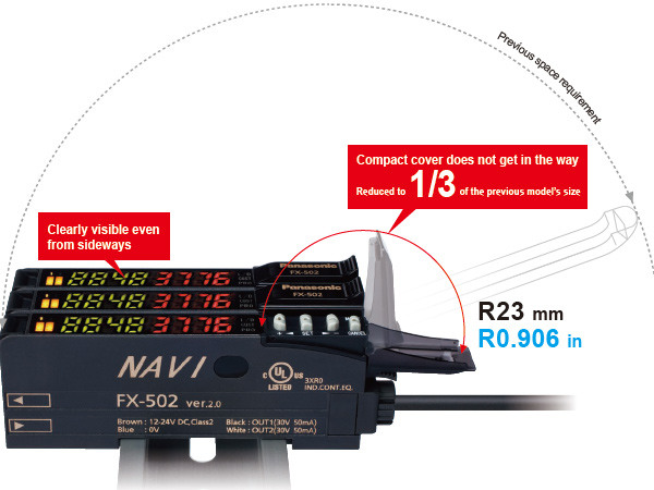
Flat display with wide viewing angle
The large and high-contrast 7-segment display of high luminance provides clear visibility from a wide angle of view.
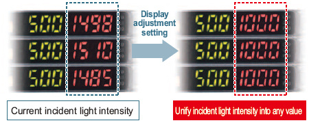
Resolves variation in displayed incident light intensity
Display adjustment setting
The variation in display can be adjusted to random values. This helps to define proper instruction in a work order.
Stable detection over long and short periods
Stabilized emission amount
The "four-chemical emitting element", which we are the first to incorporate to maintain a stable level of light emission, has now become an industry standard.
FX-500 series continues to adopt the same emitting element as well as the "APC (Auto Power Control) circuit" which improves stability in short periods such as when the power is turned on.
Saves maintenance time
Threshold tracking function
This function performs automatic setting to threshold value by checking the incident light intensity at desired intervals in order to follow the changes in the light amount resulting from changes in the environment over long periods (such as dust). This contributes to reduction in maintenance hours.
■Detect deterioration in light intensity
(e.g. Useful in dusty environment)
Self-diagnosis can be used with the threshold tracking function for added effectiveness.
Suitable for preventative maintenance
Self-diagnosis output [FX-502(P), FX-505(P)-C2]
FX-502(P) / 505(P)-C2 can set Output 2 as a selfdiagnosis output. When the teaching of Output 1's threshold value is carried out, Output 2 is set concurrently with the setting randomly shifted by the amount of surplus of threshold value. Light intensity deterioration due to fiber breakage or dust accumulation can be notified as an alarm output.
Stable detection while being eco-friendly
Emission power & gain setting
In cases when the incident light intensity is saturated, the light emitting amount can be adjusted to the optimal level by AUTO without changing the response time. This allows stable detection with an optimal S/N ratio and saves energy by controlling the emitting electric current.
![Auto mode (AUTO) and 3-level manual mode (H / M / L [fine-adjustable]) are incorporated.](https://ap.industry.panasonic.com/hubfs/pid-corp/products/fasys/sensor/fiber/fx-500/images/pic14.jpg)
Detecting a transparent sheet
Built-in logic functions
No PLC necessary, saving material and programming costs
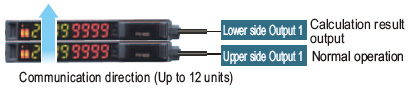
■Logical calculation functions
3 logical calculations (AND, OR, XOR) are available with fiber sensor only. 3 logical operations can be selected against Output 1. Additional controller is not required so both wire-saving and cost reduction can be achieved.
[Calculation of two neighboring amplifiers]
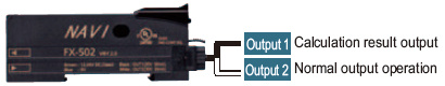
[Calculation of two outputs in one amplifier](FX-502(P) / 505(P)-C2)
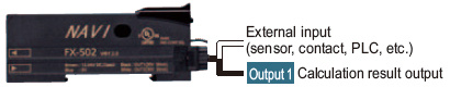
[Calculation of one amplifier and external input](FX-502(P) / 505(P)-C2)
Truth table
| A | B | Logical calculation output (C) | ||
|---|---|---|---|---|
| AND | OR | XOR | ||
| ON | ON | ON | ON | OFF |
| OFF | ON | OFF | ON | ON |
| ON | OFF | OFF | ON | ON |
| OFF | OFF | OFF | OFF | |
■Equipped with 5 timer types
A wide variety of timer control operations can be carried out by
fiber sensors only.

Timer period: 0.05 ms to 32 sOutput 1 has ON / OFF-delay and ON-delay / One-shot timers are available.
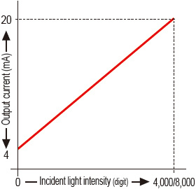
Analog output cable type [FX-505(P)-C2]
To monitor the sensing of objects, a 4 to 20 mA analog current is output in respond to the digital value of the incident light intensity.
■Edge tracking of film or sheet
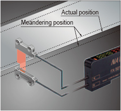
The meandering path can be monitored as the light intensity changes.
Smooth setup changes by 8 data banks
The number of data banks used for saving the setup conditions of the amplifirer is increased to eight. Setup conditions can be saved and loaded to make setup changes easy at a worksite where multiple models are manufactured.
Remote control improves work efficiency by external input [FX-502(P), FX-505(P)-C2]
Work efficiency can be improved by operating via PLC output or other external signal.*
*FX-502(P) can operate via external signal when switching from Output 2 to external input.
■Functions operable by external input
| Full-auto* / Limit* / 2-point teaching* | Display adjustment setting* |
| Data bank load* / save* | Logical calculation (self-unit only) |
| Emission halt | Copying function lock (self-unit only) |
*
FX-505(P)-C2 can obtain answer back output after external input, when sensing output 2 is set to answer back output mode.
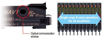
An optical communication function allows sensors to be adjusted simultaneously
The data that is currently set can be copied and saved all at once for all amplifiers connected together from the right side thanks to the optical communication function.
This greatly reduces troublesome setup tasks and makes setup much smoother.
No need to specify a main unit or sub unit
All FX-500 amplifiers can be used as either a main unit or a sub unit. Just use a main cable or a sub cable to distinguish the two. This reduces the costs of inventory management.
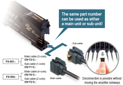
Wire-saving, space-saving
The quick-connection cables enable reduction in wiring. The connections and man-hours required for the relay terminal block setup can be reduced and valuable space is saved.
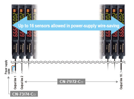
* Connection of up to 16 units with FX-400 / DPS-400 / LS-400 is possible.* Up to 12 sensors in optical communication.
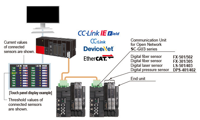
Network communication
Connection to CC-Link IE Field / CC-Link / DeviceNet / EtherCAT open network is possible through the communication unit for open network, SC-GU3 series.
Monitoring or setting changes can be carried out via a PLC, PC, etc.
*CC-Link IE Field and CC-Link are trademarks of Mitsubishi Electric Corporation, and are controlled by the CC-Link Partner Association.DeviceNet is a registered trademark of Open DeviceNet Vendor Association (ODVA), Inc.EtherCAT is a registered trademark of Beckhoff Automation GmbH.
Order guide
Amplifiers
Quick-connection cable is not supplied with FX-501(P) and FX-502(P). Please order it separately.
| Type | Appearance | Model No. | Emitting element | Output | External input |
|---|---|---|---|---|---|
| Standard type |
| FX-501 | Red LED | NPN open-collector transistor | - |
| FX-501P | PNP open-collector transistor | ||||
| 2-output type | FX-502 | NPN open-collector transistor 2 outputs | Incorporated (Switchable with Output 2) | ||
| FX-502P | PNP open-collector transistor 2 outputs | ||||
| Cable type |
| FX-505-C2 | NPN open-collector transistor 2 outputs analog output | Incorporated | |
| FX-505P-C2 | PNP open-collector transistor 2 outputs analog output |
Quick-connection cables for FX-501(P)
Quick-connection cable is not supplied with the amplifier. Please order it separately.
| Type | Model No. | Description | |
|---|---|---|---|
| Main cable (3-core) | CN-73-C1 | Length: 1 m 3.281 ft | 0.2 mm2 3-core cabtyre cable, with connector on one end Cable outer diameter: ø3.3 mm ø0.130 in |
| CN-73-C2 | Length: 2 m 6.562 ft | ||
| CN-73-C5 | Length: 5 m 16.404 ft | ||
| Sub cable (1-core) | CN-71-C1 | Length: 1 m 3.281 ft | 0.2 mm2 1-core cabtyre cable, with connector on one end Cable outer diameter: ø3.3 mm ø0.130 in |
| CN-71-C2 | Length: 2 m 6.562 ft | ||
| CN-71-C5 | Length: 5 m 16.404 ft | ||
(Note):
The material of Quick-connection cable will be changed from production in March 2013, as soon as the previous ones are shipped out.
・Conductor cross-sectional area has been changed from 0.15mm2 to 0.2mm2.
・Sheath diameter has been changed from ø3.0mm to ø3.3mm.
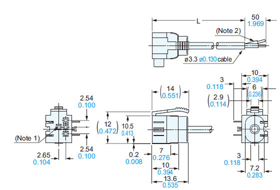
Main cable
CN-73-C□

Sub cable
CN-71-C□

Quick-connection cables for FX-502(P)
Quick-connection cable is not supplied with the amplifier. Please order it separately.
| Type | Model No. | Description | |
|---|---|---|---|
| Main cable (4-core) | CN-74-C1 | Length: 1 m 3.281 ft | 0.2 mm2 4-core cabtyre cable, with connector on one end Cable outer diameter: ø3.3 mm ø0.130 in |
| CN-74-C2 | Length: 2 m 6.562 ft | ||
| CN-74-C5 | Length: 5 m 16.404 ft | ||
| Sub cable (2-core) | CN-72-C1 | Length: 1 m 3.281 ft | 0.2 mm2 2-core cabtyre cable, with connector on one end Cable outer diameter: ø3.3 mm ø0.130 in |
| CN-72-C2 | Length: 2 m 6.562 ft | ||
| CN-72-C5 | Length: 5 m 16.404 ft | ||
(Note):
The material of Quick-connection cable will be changed from production in March 2013, as soon as the previous ones are shipped out.
・Conductor cross-sectional area has been changed from 0.15mm2 to 0.2mm2.
・Sheath diameter has been changed from ø3.0mm to ø3.3mm.
Main cable
CN-74-C□
Sub cable
CN-72-C□

End plates
End plates are not supplied with the amplifier. Please order them separately when the amplifiers are mounted in cascade.
| Appearance | Model No. | Description |
|---|---|---|
| MS-DIN-E | When cascading multiple amplifiers, or when it moves depending on the way it is installed on a DIN rail, these end plates clamp amplifiers into place on both sides. Make sure to use end plates when cascading multiple amplifiers together. [2 pcs. per set] |

Option
| Designation | Model No. | Description |
|---|---|---|
| Amplifier mounting bracket | MS-DIN-2 | Mounting bracket for amplifier |
Amplifier mounting bracket
MS-DIN-2
Accessory
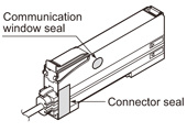
• FX-MB1 (Amplifier protection seal) 10 sets of 2 communication window seals and 1 connector seal
Others
Please refer to "Fiber Options" for details of fiber lenses and other options.
Dimensions
- Unit: mm in
FX-501(P)
FX-502(P)
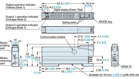
Amplifier
Notes:1) FX-502(P) only2) FX-501(P): Operation indicator3) FX-501(P): 3-pin, FX-502(P): 4-pin*The shape of setting switch will be changed from production at November, 2011. Please see drawing below.
Before the modification
Notes:1) FX-502(P) only2) FX-501(P): Operation indicator3) FX-501(P): 3-pin, FX-502(P): 4-pin
FX-505-C2
FX-505P-C2
Amplifier
Note: The shape of setting switch and cable will be changed from production at November, 2011. Please see drawing below.
Before the modification

CN-73-C□
CN-74-C□
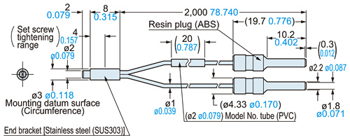
Main cable (Optional)
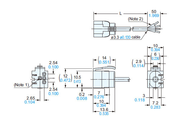
Notes:1) CN-74-C□ only2) CN-73-C□: 3-core
• Length L
| Model No. | sample |
|---|---|
| CN-73/74-C1 | 1,000 39.370 |
| CN-73/74-C2 | 2,000 78.740 |
| CN-73/74-C5 | 5,000 196.850 |
CN-71-C□
CN-72-C□
Sub cable (Optional)
Notes:1) CN-72-C□ only2) CN-71-C□: 1-core
• Length L
| Model No. | sample |
|---|---|
| CN-71/72-C1 | 1,000 39.370 |
| CN-71/72-C2 | 2,000 78.740 |
| CN-71/72-C5 | 5,000 196.850 |
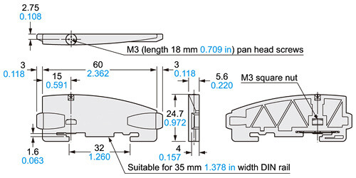
MS-DIN-2
Amplifier mounting bracket (Optional)
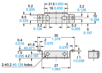
Material: Cold rolled carbon steel (SPCC) (Uni-chrome plated)
MS-DIN-E
End plate (Optional)
Material: Polycarbonate
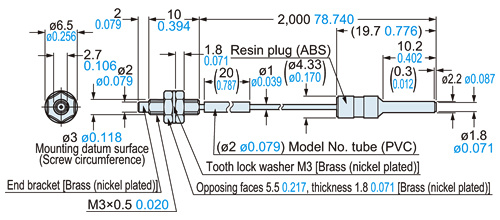
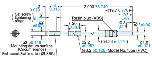
FT-30
Super quality fibers・Thru-beam type
<with FX-AT2>
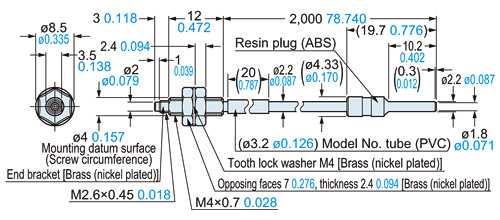
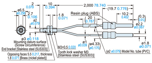
FT-40
Super quality fibers・Thru-beam type
<with FX-AT2>
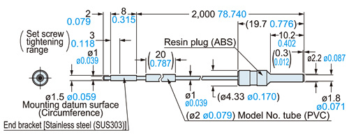
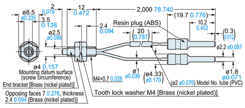
FT-S20
Super quality fibers・Thru-beam type
<with FX-AT2>
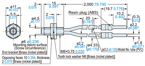
FT-S30
Super quality fibers・Thru-beam type
<with FX-AT2>
FD-30
Super quality fibers・Reflective type
<with FX-AT2>
FD-40
Super quality fibers・Reflective type
<with FX-AT2>
FD-60
Super quality fibers・Reflective type
<with FX-AT2>
FD-S30
Super quality fibers・Reflective type
<with FX-AT2>
I/O Circuit and Wiring diagrams
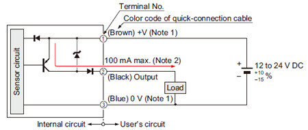
FX-501
NPN output type
I/O circuit diagram
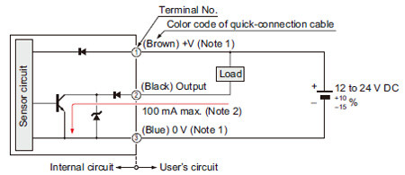
Notes:
1)The quick-connection sub cable does not have +V (brown) and 0 V (blue). The power is supplied from the connector of the main cable.
2)50 mA max., if five amplifiers or more, are connected together.
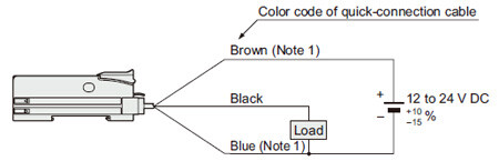
Wiring diagram
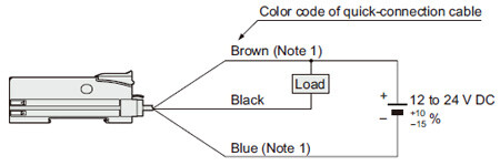
Note:
The quick-connection sub cable does not have a brown and a blue lead wire.
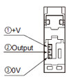
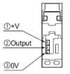
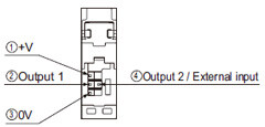
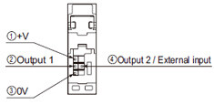
Terminal arrangement diagram
FX-501P
PNP output type
I/O circuit diagram
Notes:
1)The quick-connection sub cable does not have +V (brown) and 0 V (blue). The power is supplied from the connector of the main cable.
2)50 mA max., if five amplifiers or more, are connected together.
Wiring diagram
Note:The quick-connection sub cable does not have a brown and a blue lead wire.
Terminal arrangement diagram
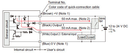
FX-502
NPN output type
I/O circuit diagram
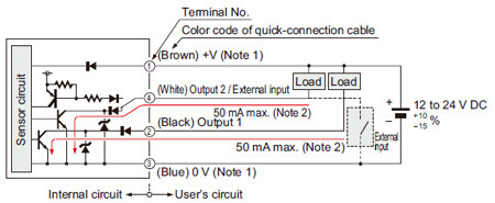
Notes:
1)The quick-connection sub cable does not have +V (brown) and 0 V (blue). The power is supplied from the connector of the main cable.
2)25 mA max., if five amplifiers or more, are connected together.
Wiring diagram
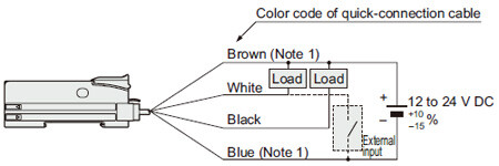
Note:The quick-connection sub cable does not have a brown and a blue lead wire.
Terminal arrangement diagram
FX-502P
PNP output type
I/O circuit diagram
Notes:
1)The quick-connection sub cable does not have +V (brown) and 0 V (blue). The power is supplied from the connector of the main cable.
2)25 mA max., if five amplifiers or more, are connected together.
Wiring diagram
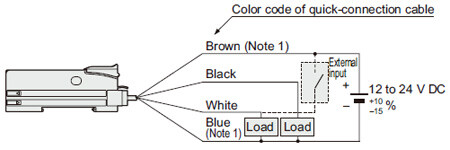
Note:The quick-connection sub cable does not have a brown and a blue lead wire.
Terminal arrangement diagram
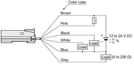
FX-505-C2
NPN output type
I/O circuit diagram
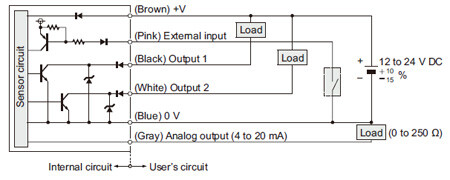
Wiring diagram
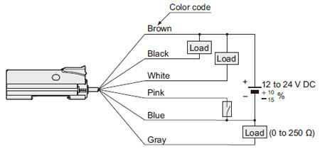
FX-505P-C2
PNP output type
I/O circuit diagram
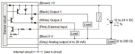
Wiring diagram
List of fibers
Response time of FX-500 series.
| Mode | HYPR | U-LG | LONG | STD | FAST | H-SP |
|---|---|---|---|---|---|---|
| Response time | 24ms or less | 4ms or less | 2ms or less | 250μs or less | 60μs or less | 25μs or less |
List of fiber
- Chemical-resistant
- Heat-resistant
- One-Touch Connection System Vacuum-resistant Fibers
- Vacuum-resistant
- Discontinued products
Square Head Fiber
■Thru-beam type(one pair set)
| Type | Model No. | Sensing range(mm) (Note1) | ||||||
|---|---|---|---|---|---|---|---|---|
| HYPR | U-LG | LONG | STD | FAST | H-SP | |||
| Square head | M3 | FT-R31 | 1,000 | 580 | 440 | 270 | 160 | 55 |
| M4 | FT-R43 | 3,000 | 1,600 | 1,100 | 720 | 430 | 130 | |
| FT-R41W | 3,200 | 1,800 | 1,400 | 800 | 460 | 150 | ||
| FT-R42W | 3,600 (Note2) | 3,600 (Note2) | 3,500 | 2,200 | 1,300 | 460 | ||
| FT-R44Y | 3,000 | 1,600 | 1,100 | 720 | 430 | 130 | ||
| M6 | FT-R60Y | 3,600 (Note2) | 3,600 (Note2) | 3,600 (Note2) | 2,100 | 1,260 | 400 | |
Note1:Note that sensing range of the free-cut type fiber may be reduced by 20 % max. depending upon how the fiber is cut.
Note2:The fiber cable length practically limits the sensing range.
■Reflective type
| Type | Model No. | Sensing range(mm) (Note1) (Note2) | ||||||
|---|---|---|---|---|---|---|---|---|
| HYPR | U-LG | LONG | STD | FAST | H-SP | |||
| Square head | M3 | FD-R31G | 530 | 310 | 260 | 170 | 85 | 27 |
| FD-R32EG | 170 | 110 | 92 | 45 | 30 | 9 | ||
| FD-R34EG | 130 | 90 | 70 | 38 | 23 | 7 | ||
| FD-R33EG | 84 | 44 | 33 | 19 | 11 | 3 | ||
| M4 | FD-R41 | 710 | 430 | 320 | 210 | 100 | 34 | |
| M6 | FD-R61Y | 990 | 610 | 435 | 280 | 160 | 50 | |
Note1:Note that sensing range of the free-cut type fiber may be reduced by 20 % max. depending upon how the fiber is cut.
Note2:The sensing range is specified for white non-glossy paper.
For details of Square Head Fiber, refer to product information page.
>>Go to "Square Head Fiber"
Super Quality

■Thru-beam type (one pair set)
| Type | Model No. | Sensing range (mm) | ||||||
|---|---|---|---|---|---|---|---|---|
| HYPR | U-LG | LONG | STD | FAST | H-SP | |||
| Threaded | M3 | FT-30 | 1,350 | 810 | 650 | 400 | 210 | 75 |
| M4 | FT-40 | 3,600 (Note) | 2,200 | 1,700 | 1,200 | 530 | 190 | |
| Cylindrical | φ1.5 | FT-S20 | 1,350 | 810 | 650 | 400 | 210 | 75 |
| φ3 | FT-S30 | 3,600 (Note) | 2,200 | 1,700 | 1,200 | 530 | 190 | |
Note:The fiber cable length practically limits the sensing range.
■Reflective type
| Type | Model No. | Sensing range (mm) (Note) | ||||||
|---|---|---|---|---|---|---|---|---|
| HYPR | U-LG | LONG | STD | FAST | H-SP | |||
| Threaded | M3 | FD-30 | 600 | 330 | 250 | 160 | 80 | 25 |
| M4 | FD-40 | 600 | 330 | 250 | 160 | 80 | 25 | |
| M6 | FD-60 | 1,550 | 900 | 740 | 520 | 260 | 90 | |
| Cylindrical | φ3 | FD-S30 | 600 | 330 | 250 | 160 | 80 | 25 |
Note:The sensing range is specified for white non-glossy paper.
For details of Super Quality Fiber, refer to product information page.
>>Go to "Super Quality Fiber"
Threaded Type
■Thru-beam type (one pair set)
| Type | Model No. | Sensing range (mm) (Note 1) | |||||||
|---|---|---|---|---|---|---|---|---|---|
| HYPR | U-LG | LONG | STD | FAST | H-SP | ||||
| Threaded | M3 | FT-31 | 1,350 | 770 | 550 | 315 | 210 | 70 | |
| FT-31W | 990 | 590 | 440 | 260 | 150 | 53 | |||
| FT-32 | 3,600 (Note 2) | 3,600 (Note 2) | 3,600 (Note 2) | 3,000 | 1,600 | 580 | |||
| M4 | FT-43 | 3,600 (Note 2) | 2,800 | 2,100 | 1,400 | 770 | 240 | ||
| FT-42 | 3,600 (Note 2) | 2,050 | 1,600 | 1,130 | 530 | 190 | |||
| FT-42W | 3,300 | 1,900 | 1,400 | 800 | 490 | 160 | |||
| FT-45X | 1,600 (Note 2) | 1,600 (Note 2) | 1,600 (Note 2) | 1,200 | 630 | 200 | |||
| Elbow | FT-R40 | 3,600 (Note 2) | 1,750 | 1,500 | 930 | 500 | 160 | ||
| M14 | Long range | FT-140 | 19,600 (Note 2) | 19,600 (Note 2) | 19,600 (Note 2) | 19,600 (Note 2) | 16,000 | 6,300 | |
Note 1:Note that the sensing range of the free-cut type fiber may be reduced by 20 % max. depending upon how the fiber is cut.
Note 2:The fiber cable length practically limits the sensing range.
■Reflective type
| Type | Model No. | Sensing range (mm) (Note 1, 2) | |||||||
|---|---|---|---|---|---|---|---|---|---|
| HYPR | U-LG | LONG | STD | FAST | H-SP | ||||
| Threaded | M3 | FD-31 | 515 | 290 | 220 | 125 | 80 | 25 | |
| FD-31W | 330 | 180 | 140 | 80 | 45 | 12 | |||
| FD-32G | 650 | 380 | 270 | 200 | 95 | 27 | |||
| FD-32GX | 630 | 410 | 360 | 200 | 100 | 30 | |||
| FD-34G | 330 | 185 | 135 | 90 | 49 | 15 | |||
| Ultra-small diameter | FD-EG30 | 170 | 130 | 110 | 48 | 30 | 9 | ||
| FD-EG31 | 85 | 45 | 35 | 20 | 12 | 3.5 | |||
| M4 | FD-41 | 515 | 290 | 220 | 125 | 80 | 25 | ||
| FD-41W | 900 | 630 | 430 | 270 | 150 | 45 | |||
| FD-42G | 650 | 380 | 270 | 200 | 95 | 27 | |||
| FD-42GW | 670 | 340 | 280 | 150 | 90 | 25 | |||
| M6 | FD-62 | 1,500 | 1,000 | 940 | 520 | 340 | 110 | ||
| FD-61 | 1,400 | 840 | 670 | 450 | 200 | 70 | |||
| FD-61W | 900 | 630 | 430 | 270 | 150 | 45 | |||
| FD-61G (Discontinued products) | 1,100 | 800 | 650 | 420 | 200 | 60 | |||
| FD-64X | 670 | 500 | 410 | 280 | 160 | 50 | |||
| Elbow | FD-R60 | 1,100 | 600 | 550 | 290 | 190 | 65 | ||
Note 1:Note that the sensing range of the free-cut type fiber may be reduced by 20 % max. depending upon how the fiber is cut.
Note 2:The sensing range is specified for white non-glossy paper.
For details of Threaded Type Fiber, refer to product information page.
>>Go to "Threaded Type Fiber"
Cylindrical Type
■Thru-beam type (one pair set)
| Type | Model No. | Sensing range (mm) (Note 1) | |||||||
|---|---|---|---|---|---|---|---|---|---|
| HYPR | U-LG | LONG | STD | FAST | H-SP | ||||
| Cylindrical | φ1 | FT-S11 | 350 | 210 | 160 | 90 | 60 | 19 | |
| φ1.5 | FT-S21 | 1,350 | 770 | 550 | 315 | 210 | 70 | ||
| FT-S21W | 990 | 590 | 440 | 260 | 150 | 53 | |||
| FT-S22 | 1,500 | 920 | 730 | 450 | 250 | 90 | |||
| φ2.5 | FT-S32 | 3,600 (Note 2) | 3,600 (Note 2) | 3,600 (Note 2) | 3,100 | 1,800 | 600 | ||
| φ3 | FT-S31W | 3,300 | 1,900 | 1,400 | 800 | 490 | 160 | ||
| Ultra-small diameter | φ3 | FT-E13 | 52 | 30 | 24 | 15 | 8 | 2 | |
| FT-E23 | 270 | 160 | 125 | 75 | 42 | 13 | |||
| Side-view | φ4 | FT-V40 | 3,600 (Note 2) | 3,600 (Note 2) | 3,600 (Note 2) | 3,500 | 2,400 | 850 | |
Note 1:Note that the sensing range of the free-cut type fiber may be reduced by 20 % max. depending upon how the fiber is cut.
Note 2:The fiber cable length practically limits the sensing range.
■Reflective type
| Type | Model No. | Sensing range (mm) (Note 1, 2) | |||||||
|---|---|---|---|---|---|---|---|---|---|
| HYPR | U-LG | LONG | STD | FAST | H-SP | ||||
| Cylindrical | φ1.5 | FD-S21 (Discontinued Products) | 190 | 130 | 110 | 80 | 37 | 11 | |
| FD-S23 | 130 | 90 | 65 | 46 | 20 | 7 | |||
| φ3 | FD-S32 | 1200 | 790 | 660 | 420 | 220 | 75 | ||
| FD-S32W | 900 | 630 | 430 | 270 | 150 | 45 | |||
| FD-S31 | 515 | 290 | 220 | 125 | 80 | 25 | |||
| FD-S33GW | 670 | 340 | 280 | 150 | 90 | 25 | |||
| FD-S34G | 330 | 185 | 135 | 90 | 49 | 15 | |||
| Ultra-small diameter | φ1.5 | FD-E13 | 50 | 29 | 25 | 12 | 7 | 2 | |
| φ3 | FD-E23 | 170 | 120 | 80 | 55 | 30 | 9 | ||
Note 1:Note that the sensing range of the free-cut type fiber may be reduced by 20 % max. depending upon how the fiber is cut.
Note 2:The sensing range is specified for white non-glossy paper.
For details of Cylindrical Type Fiber, refer to product information page.
>>Go to "Cylindrical Type Fiber"
Sleeve

■Thru-beam type (one pair set)
| Type | Model No. | Sensing range (mm) (Note 1, 2) | |||||||
|---|---|---|---|---|---|---|---|---|---|
| HYPR | U-LG | LONG | STD | FAST | H-SP | ||||
| Threaded | M3 | FT-31S | 1,220 | 740 | 550 | 315 | 195 | 63 | |
| M4 | FT-42S | 3,600 (Note 2) | 2,050 | 1,600 | 1,130 | 530 | 190 | ||
| Cylindrical | Ultra-small diameter | φ3 | FT-E13 | 52 | 30 | 24 | 15 | 8 | 2 |
| FT-E23 | 270 | 160 | 125 | 75 | 42 | 13 | |||
| Side-view | φ2 | FT-V23 | 1,800 | 1,000 | 880 | 450 | 280 | 90 | |
| FT-V25 | 900 | 550 | 480 | 240 | 140 | 45 | |||
| FT-V24W | 380 | 230 | 200 | 110 | 60 | 20 | |||
| φ2.5 | FT-V30 | 2,200 | 1,200 | 1,000 | 680 | 340 | 100 | ||
Note 1:Note that the sensing range of the free-cut type fiber may be reduced by 20 % max. depending upon how the fiber is cut.
Note 2:The fiber cable length practically limits the sensing range.
■Reflective type
| Type | Model No. | Sensing range (mm) (Note 1, 2) | |||||||
|---|---|---|---|---|---|---|---|---|---|
| HYPR | U-LG | LONG | STD | FAST | H-SP | ||||
| Threaded | Ultra-small diameter | M3 | FD-EG30S | 170 | 110 | 80 | 50 | 30 | 9 |
| M4 | FD-41S | 515 | 290 | 220 | 125 | 80 | 25 | ||
| FD-41SW | 330 | 180 | 140 | 80 | 45 | 12 | |||
| M6 | FD-61S | 1,200 | 790 | 660 | 420 | 220 | 75 | ||
| Cylindrical | Ultra-small diameter | φ1.5 | FD-E13 | 50 | 29 | 25 | 12 | 7 | 2 |
| φ3 | FD-E23 | 170 | 120 | 80 | 55 | 30 | 9 | ||
| Side-view | φ3 | FD-V30 | 240 | 130 | 120 | 65 | 35 | 14 | |
| FD-V30W | 80 | 40 | 30 | 20 | 10 | 2 | |||
| φ5 | FD-V50 | 370 | 220 | 210 | 120 | 75 | 25 | ||
Note 1:Note that the sensing range of the free-cut type fiber may be reduced by 20 % max. depending upon how the fiber is cut.
Note 2:The sensing range is specified for white non-glossy paper.
For details of Sleeve Fiber, refer to product information page.
>>Go to "Sleeve Fiber"
Flat Type
■Thru-beam type (one pair set)
| Type | Model No. | Sensing range (mm) (Note 1) | ||||||
|---|---|---|---|---|---|---|---|---|
| HYPR | U-LG | LONG | STD | FAST | H-SP | |||
| Flat | FT-Z30H | 3,600 (Note 2) | 3,600 (Note 2) | 3,600 (Note 2) | 3,500 | 2,600 | 810 | |
| FT-Z30HW | 3,600 (Note 2) | 3,600 (Note 2) | 3,600 (Note 2) | 3,500 | 2,600 | 810 | ||
| FT-Z30E | 3,600 (Note 2) | 3,600 (Note 2) | 3,600 (Note 2) | 3,500 | 2,400 | 740 | ||
| FT-Z30EW | 3,600 (Note 2) | 3,600 (Note 2) | 3,600 (Note 2) | 3,400 | 2,000 | 630 | ||
| FT-Z30 | 3,600 (Note 2) | 3,600 (Note 2) | 3,600 (Note 2) | 2,100 | 1,200 | 410 | ||
| FT-Z30W | 3,600 (Note 2) | 3,300 | 3,200 | 1,500 | 1,000 | 280 | ||
| With boss | FT-Z20W | 1,600 (Note 2) | 1,500 | 1,100 | 620 | 420 | 130 | |
| FT-Z20HBW | 1,100 | 670 | 570 | 260 | 180 | 55 | ||
| FT-Z40W | 3,600 (Note 2) | 3,300 | 2,300 | 1,500 | 900 | 290 | ||
| FT-Z40HBW | 3,300 | 1,900 | 1,400 | 800 | 490 | 160 | ||
Note 1:Note that the sensing range of the free-cut type fiber may be reduced by 20 % max. depending upon how the fiber is cut.
Note 2:The fiber cable length practically limits the sensing range.
■Reflective type
| Type | Model No. | Sensing range (mm) (Note 1, 2) | ||||||
|---|---|---|---|---|---|---|---|---|
| HYPR | U-LG | LONG | STD | FAST | H-SP | |||
| Flat | With boss | FD-Z20W | 260 | 150 | 130 | 1 to 65 | 2 to 45 | 5 to 13 |
| FD-Z20HBW | 1 to 340 | 1 to 210 | 1 to 180 | 2 to 85 | 2 to 55 | 3 to 15 | ||
| FD-Z40W | 790 | 440 | 390 | 190 | 1 to 120 | 2 to 35 | ||
| FD-Z40HBW | 760 | 540 | 470 | 260 | 1 to 160 | 2 to 50 | ||
Note 1:Note that the sensing range of the free-cut type fiber may be reduced by 20 % max. depending upon how the fiber is cut.
Note 2:The sensing range is specified for white non-glossy paper.
For details of Flat Type Fiber, refer to product information page.
>>Go to "Flat Type Fiber"
Narrow Beam
■Thru-beam type (one pair set)
| Type | Model No. | Sensing range (mm) (Note 1) | |||||
|---|---|---|---|---|---|---|---|
| HYPR | U-LG | LONG | STD | FAST | H-SP | ||
| Narrow beam | FT-KS40 | 3,600 (Note 2) | 3,600 (Note 2) | 3,600 (Note 2) | 3,600 (Note 2) | 3,600 (Note 2) | 1,200 |
| FT-KV40 | 3,600 (Note 2) | 3,600 (Note 2) | 3,600 (Note 2) | 3,600 (Note 2) | 3,100 | 940 | |
| FT-KV40W | 3,600 (Note 2) | 3,600 (Note 2) | 3,600 (Note 2) | 3,600 (Note 2) | 3,100 | 940 | |
| FT-KV26 | 2,500 | 1,600 | 1,200 | 710 | 440 | 160 | |
| FT-KV26H1 | 2,200 | 1,430 | 1,070 | 630 | 390 | 135 | |
Note 1:Note that the sensing range of the free-cut type fiber may be reduced by 20 % max. depending upon how the fiber is cut.
Note 2:The fiber cable length practically limits the sensing range.
■Retroreflective type
| Type | Model No. | Sensing range (mm) (Note 1, 2) | ||||||
|---|---|---|---|---|---|---|---|---|
| HYPR | U-LG | LONG | STD | FAST | H-SP | |||
| With polarizing filters | FR-Z50HW | 100 to 1,900 | 100 to 1,400 | 100 to 1,200 | 100-990 | 100 to 780 | 100 to 490 | |
| Wafer mapping | FR-KZ22E | 15 to 570 | 15 to 460 | 15 to 410 | 15 to 310 | 15 to 220 | 15 to 100 | |
| Narrow beam | Top sensing | FR-KZ50H | 20 to 1,000 | 20 to 800 | 20 to 400 | 20 to 300 | 20 to 200 | 20 to 200 |
| Side sensing | FR-KZ50E | 20 to 1,000 | 20 to 800 | 20 to 400 | 20 to 300 | 20 to 200 | 20 to 200 | |
Note 1:Note that the sensing range of the free-cut type fiber may be reduced by 20 % max. depending upon how the fiber is cut.
Note 2:The sensing range is the possible setting range for the attached reflector. The fiber can detect an object less than setting range for the reflector.
■Reflective type
| Type | Model No. | Sensing range (mm) (Note) | |||||
|---|---|---|---|---|---|---|---|
| HYPR | U-LG | LONG | STD | FAST | H-SP | ||
| Long range | FD-Z50HW | 10 to 2,500 | 10 to 1,100 | 10 to 1,000 | 10 to 650 | 10 to 410 | 15 to 130 |
Note:Note that the sensing range of the free-cut type fiber may be reduced by 20 % max. depending upon how the fiber is cut.
For details of Narrow Beam Fiber, refer to product information page.
>>Go to "Narrow Beam Fiber"
Wide Beam
■Thru-beam type (one pair set)
| Type | Model No. | Sensing range (mm) (Note 1) | |||||
|---|---|---|---|---|---|---|---|
| HYPR | U-LG | LONG | STD | FAST | H-SP | ||
| Wide beam | FT-A32 | 3,600 (Note 2) | 3,600 (Note 2) | 3,600 (Note 2) | 3,600 (Note 2) | 3,600 (Note 2) | 2,100 |
| FT-A32W | 3,600 (Note 2) | 3,600 (Note 2) | 3,600 (Note 2) | 3,600 (Note 2) | 3,600 (Note 2) | 3,000 | |
| FT-A11 | 3,600 (Note 2) | 3,600 (Note 2) | 3,600 (Note 2) | 3,600 (Note 2) | 3,600 (Note 2) | 1,100 | |
| FT-A11W | 3,600 (Note 2) | 3,600 (Note 2) | 3,600 (Note 2) | 3,600 (Note 2) | 3,600 (Note 2) | 1,300 | |
| Array | FT-AL05 | 2,300 | 1,550 | 1,500 | 860 | 500 | 170 |
Note 1:Note that the sensing range of the free-cut type fiber may be reduced by 20 % max. depending upon how the fiber is cut.
Note 2:The fiber cable length practically limits the sensing range to 3,600 mm long.
■Reflective type
| Type | Model No. | Sensing range (mm) (Note 1, 2) | |||||
|---|---|---|---|---|---|---|---|
| HYPR | U-LG | LONG | STD | FAST | H-SP | ||
| Wide beam | FD-A16 | - | 200 | 200 | 200 | 140 | 75 |
| Array | FD-AL11 (Discontinued Products) | 670 | 530 | 510 | 320 | 180 | 50 |
| FD-AL12 | 670 | 530 | 420 | 270 | 150 | 50 | |
Note 1:Note that the sensing range of the free-cut type fiber may be reduced by 20 % max. depending upon how the fiber is cut.
Note 2:The sensing range is specified for white non-glossy paper.
For details of Wide Beam Fiber, refer to product information page.
>>Go to "Wide Beam Fiber"
Convergent Reflective Type

■Reflective type
| Type | Model No. | Sensing range (mm) (Note 1, 2) | |||||
|---|---|---|---|---|---|---|---|
| HYPR | U-LG | LONG | STD | FAST | H-SP | ||
| Glass substrate detection | FD-L32H | 0 to 110 | 0 to 87 | 0 to 74 | 0 to 56 | 1 to 38 | - |
| FD-L30A | 0 to 43 | 0 to 43 | 0 to 43 | 0 to 43 | 0 to 42 | 0 to 29 | |
| FD-L31A | 3 to 35 | 4 to 33 | 4 to 33 | 4 to 33 | 4 to 32 | 5 to 25 | |
| FD-L22A (Discontinued Products) | 0 to 31 | 0 to 28 | 0 to 27 | 0 to 24 | 0 to 24 | 0 to 18 | |
| FD-L24A | 0 to 31 | 0 to 28 | 0 to 26 | 0 to 23 | 0 to 22 | 0 to 18 | |
| FD-L23 (Discontinued Products) | 0 to 30 | 0 to 30 | 0 to 30 | 0 to 29 | 0 to 28 | 1.5 to 24 | |
| FD-L25 | 0 to 30 | 0 to 30 | 0 to 30 | 0 to 29 | 0 to 28 | 2 to 23 | |
| FD-L11 | 0 to 11.5 | 0 to 10.5 | 0 to 10 | 0 to 9.5 | 0 to 9 | 0 to 8 | |
| FD-L10 | 0 to 6 | 0 to 5.5 | 0 to 5.5 | 0 to 5 | 0 to 4.5 | 0 to 4 | |
| FD-L21 | 1 to 19 | 1 to 18 | 1 to 18 | 1.5 to 16 | 2 to 15 | 3 to 12 | |
| FD-L21W | 1.5 to 15 | 2 to 15 | 2 to 15 | 3 to 14 | 4 to 14 | 6.5 to 10 | |
| General purpose | FD-L20H | 0 to 45 | 0 to 35 | 0 to 32 | 0 to 23 | 2 to 15 | 5 to 9 |
| Ultla-small | FD-L12W | 0 to 14 | 0 to 12.5 | 0 to 12 | 0 to 8 | 0.5 to 7 | 0.5 to 4 |
Note 1:The sensing range is specified for transparent glass 100 x 100 x t0.7 mm (FD-L32H: R edge, FD-L21 and FD-L21W: t2 mm) (FD-L20H: white non-glossy paper, FD-L10: silicon wafers 100 x 100 mm).
Note 2:Note that the sensing range of the free-cut type fiber may be reduced by 20 % max. depending upon how the fiber is cut.
For details of Convergent Reflective Type Fiber, refer to product information page.
>>Go to "Convergent Reflective Type Fiber"
Retroreflective Type

■Retroreflective type
| Type | Model No. | Sensing range (mm) (Note 1, 2) | ||||||
|---|---|---|---|---|---|---|---|---|
| HYPR | U-LG | LONG | STD | FAST | H-SP | |||
| With polarizing filters | FR-Z50HW | 100 to 1,900 | 100 to 1,400 | 100 to 1,200 | 100 to 990 | 100 to 780 | 100 to 490 | |
| Wafer mapping | FR-KZ22E | 15 to 570 | 15 to 460 | 15 to 410 | 15 to 310 | 15 to 220 | 15 to 100 | |
| Narrow beam | Top sensing | FR-KZ50H | 20 to 1,000 | 20 to 800 | 20 to 400 | 20 to 300 | 20 to 200 | 20 to 200 |
| Side sensing | FR-KZ50E | 20 to 1,000 | 20 to 800 | 20 to 400 | 20 to 300 | 20 to 200 | 20 to 200 | |
Note 1:Note that the sensing range of the free-cut type fiber may be reduced by 20 % max. depending upon how the fiber is cut.
Note 2:The sensing range is the possible setting range for the attached reflector. The fiber can detect an object less than setting range for the reflector.
For details of Retroreflective Type Fiber, refer to product information page.
>>Go to "Retroreflective Type Fiber"
Chemical-resistant

■Thru-beam type (one pair set)
| Type | Model No. | Sensing range (mm) (Note 1) | |||||
|---|---|---|---|---|---|---|---|
| HYPR | U-LG | LONG | STD | FAST | H-SP | ||
| Chemical-resistant | FT-Z802Y | 3,600 (Note 2) | 3,600 (Note 2) | 3,600 (Note 2) | 3,100 | 1,900 | 470 |
| FT-HL80Y | 3,600 (Note 2) | 3,600 (Note 2) | 3,600 (Note 2) | 3,600 (Note 2) | 2,300 | 740 | |
| FT-L80Y | 3,600 (Note 2) | 3,600 (Note 2) | 3,600 (Note 2) | 3,600 (Note 2) | 2,800 | 920 | |
| FT-V80Y | 3,600 (Note 2) | 2,800 | 2,200 | 1,300 | 800 | 240 | |
Note 1:Note that the sensing range of the free-cut type fiber may be reduced by 20 % max. depending upon how the fiber is cut.
Note 2:The fiber cable length practically limits the sensing range.
■Reflective type
| Type | Model No. | Sensing range (mm) (Note1)(Note2) | |||||
|---|---|---|---|---|---|---|---|
| HYPR | U-LG | LONG | STD | FAST | H-SP | ||
| Chemical-resistant | FD-S60Y | 600 | 590 | 420 | 320 | 200 | 75 |
Note 1:Note that the sensing range of the free-cut type fiber may be reduced by 20 % max. depending on how the fiber is cut.
Note 2:The sensing range is specified for white non-glossy paper.
For details of Chemical-resistant Fiber, refer to product information page.
>>Go to "Chemical-resistant Fiber"
Heat-resistant
■Thru-beam type (one pair set)
| Type | Heat-resistant temp. | Model No. | Sensing range (mm) (Note 1) | |||||
|---|---|---|---|---|---|---|---|---|
| HYPR | U-LG | LONG | STD | FAST | H-SP | |||
| Heat-resistant | 350℃ | FT-H35-M2 | 1,200 | 880 | 670 | 430 | 250 | 80 |
| FT-H35-M2S6 | 1,200 | 880 | 670 | 430 | 250 | 80 | ||
| 200℃ | FT-H20W-M1 | 1,600 (Note 2) | 1,000 | 840 | 470 | 300 | 90 | |
| FT-H20-M1 | 1,600 (Note 2) | 1,300 | 960 | 540 | 330 | 110 | ||
| 130℃ | FT-H13-FM2 | 3,300 | 1,900 | 1,300 | 700 | 410 | 140 | |
| Heat-resistant (joint) | 200℃ | FT-H20-J20-S | 1,600 | 1,000 | 790 | 470 | 300 | 90 |
| FT-H20-J30-S | 1,600 | 1,000 | 790 | 470 | 300 | 90 | ||
| FT-H20-J50-S | 1,600 | 1,000 | 790 | 470 | 300 | 90 | ||
| FT-H20-VJ50-S | 2,100 | 1,300 | 980 | 600 | 390 | 120 | ||
| FT-H20-VJ80-S | 2,100 | 1,300 | 980 | 600 | 390 | 120 | ||
Note 1:Note that the sensing range of the free-cut type fiber may be reduced by 20 % max. depending upon how the fiber is cut.
Note 2:The fiber cable length practically limits the sensing range.
■Reflective type
| Type | Heat-resistant temp. | Model No. | Sensing range (mm) (Note 1, 2) | ||||||
|---|---|---|---|---|---|---|---|---|---|
| HYPR | U-LG | LONG | STD | FAST | H-SP | ||||
| Heat-resistant | Threaded | 350℃ | FD-H35-M2 | 720 | 540 | 460 | 260 | 150 | 45 |
| FD-H35-M2S6 | 720 | 540 | 460 | 260 | 150 | 45 | |||
| FD-H35-20S | 840 | 550 | 440 | 260 | 140 | 45 | |||
| 200℃ | FD-H20-M1 | 840 | 550 | 500 | 330 | 200 | 55 | ||
| FD-H20-21 | 770 | 500 | 380 | 230 | 130 | 45 | |||
| 130℃ | FD-H13-FM2 | 880 | 640 | 600 | 350 | 200 | 65 | ||
| Glass substrate detection convergent reflective | 300℃ | FD-H30-L32 | 0 to 40 | 0 to 30 | 0 to 25 | 0 to 17 | 0 to 12 | 1.5 to 6 | |
| 250℃ | FD-H25-L43 | 1 to 31 | 1 to 30 | 1 to 28 | 1.5 to 26 | 1.5 to 24 | 2 to 18 | ||
| FD-H25-L45 | 4 to 43.5 | 4 to 43 | 4.5 to 43 | 5 to 42 | 5 to 40 | 6.5 to 34 | |||
| 180℃ | FD-H18-L31 | 0 to 60 | 0 to 32 | 0 to 24 | 0 to 16 | 0 to 13 | 2 to 6.5 | ||
Note 1:The sensing range of reflective type is the value for white non-glossy paper (50 x 50 mm glass substrate for FD-H30-L32 and FD-H18-L31, transparent glass 100 x 100 x t0.7 mm for FD-H25-L43 and FD-H25-L45).
Note 2:Note that the sensing range of the free-cut type fiber may be reduced by 20 % max. depending upon how the fiber is cut.
For details of Heat-resistant Fiber, refer to product information page.
>>Go to "Heat-resistant Fiber"
One-Touch Connection System Vacuum-resistant Fibers
■Thru-beam type
| Type | Model No. | Sensing range (mm)(Note 1) | ||||||
|---|---|---|---|---|---|---|---|---|
| HYPR | U-LG | LONG | STD | FAST | H-SP | |||
| Vacuum- resistant | Thru-beam | FT-40V | 1,000 | 590 | 470 | 270 | 160 | 55 |
(Note 1):Atmospheric side fiber, FT-J9 (optional) is free-cut type.
Note that the sensing range of the free-cut type fiber may be reduced by 20 % max. depending upon how the fiber is cut.
■Reflective type
| Type | Model No. | Sensing range(mm) (Note 1)(Note 2) | ||||||
|---|---|---|---|---|---|---|---|---|
| HYPR | U-LG | LONG | STD | FAST | H-SP | |||
| Vacuum- resistant | Long range reflective | FD-KZ50V | 5 to 500 | 10 to 340 | 15 to 270 | 20 to 200 | 20 to 120 | 20 to 45 |
| Convergent reflective | FD-L10V | 0 to 18 | 0 to 12 | 0 to 10 | 0 to 8 | 0 to 5.5 | 1.5 to 3 | |
(Note 1):The sensing range is the value for transparent glass 100 × 100 × t0.7 mm 3.937 × 3.937 × t0.028 in.
(Note 2):Atmospheric side fiber, FT-J9 (optional) is free-cut type.
Note that the sensing range of the free-cut type fiber may be reduced by 20 % max. depending upon how the fiber is cut.
For details of One-Touch Connection System Vacuum-resistant Fibers, refer to product information page.
>>Go to "One-Touch Connection System Vacuum-resistant Fibers"
Vacuum-resistant
■Thru-beam type (one pair set)
| Type | Model No. | Sensing range (mm) | ||||||
|---|---|---|---|---|---|---|---|---|
| HYPR | U-LG | LONG | STD | FAST | H-SP | |||
| Vacuum-resistant | Thru-beam | FT-H30-M1V-S | 1,000 | 590 | 470 | 270 | 160 | 55 |
■Reflective type
| Type | Model No. | Sensing range (mm) (Note) | ||||||
|---|---|---|---|---|---|---|---|---|
| HYPR | U-LG | LONG | STD | FAST | H-SP | |||
| Vacuum-resistant | Reflective | FD-H30-KZ1V-S | 5 to 500 | 10 to 340 | 15 to 270 | 20 to 200 | 20 to 120 | 20 to 45 |
| Convergent reflective | FD-H30-L32V-S | 0 to 18 | 0 to 12 | 0 to 10 | 0 to 8 | 0 to 5.5 | 1.5 to 3 | |
Note:The sensing range of reflective type is the value for transparent glass 100 x 100 x t0.7 mm.
For details of Vacuum-resistant Fiber, refer to product information page.
>>Go to "Vacuum-resistant Fiber"
Discontinued products
Metal-free
■Thru-beam type (one pair set)
| Type | Model No. | Sensing range (mm) (Note) | ||||||
|---|---|---|---|---|---|---|---|---|
| HYPR | U-LG | LONG | STD | FAST | H-SP | |||
| Threaded | M4 | FT-41 | 3,300 | 2,000 | 1,550 | 1,100 | 445 | 150 |
Note:Note that the sensing range of the free-cut type fiber may be reduced by 20 % max. depending upon how the fiber is cut.
■Reflective type
| Type | Model No. | Sensing range (mm) (Note 1, 2) | ||||||
|---|---|---|---|---|---|---|---|---|
| HYPR | U-LG | LONG | STD | FAST | H-SP | |||
| Threaded | M4 | FD-G40 | 550 | 330 | 270 | 140 | 80 | 27 |
| M6 | FD-G60 | 1,400 | 800 | 650 | 420 | 200 | 60 | |
Note 1:Note that the sensing range of the free-cut type fiber may be reduced by 20 % max. depending upon how the fiber is cut.
Note 2:The sensing range is specified for white non-glossy paper.
For details of Metal-free Fiber, refer to product information page.
>>Go to "Metal-free Fiber"