Digital Laser Sensor LS-400
I/O Circuit and Wiring diagrams
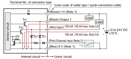
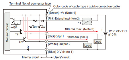
NPN output type
I/O circuit diagram
Notes:
| 1) |
The quick-connection sub cable does not have +V (brown) and 0 V (blue).The power is supplied from the connector of the main cable. |
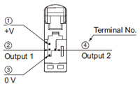
| 2) |
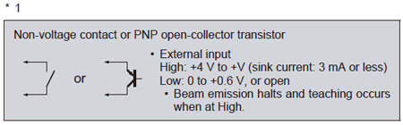
Connector type LS-401/403 does not incorporate the external input. |
| 3) |
LS-401(-C2) is 100 mA max, however, LS-401(-C2) is 50 mA max.
if 5 to 8 amplifiers are connected in cascade, and 25 mA max. if 9 to 16 amplifiers are connected in cascade. |
| 4) |
LS-403 is 50 mA max, however, it is 25 mA max. if 5 to 16 amplifiers are connected in cascade. |
| Symbols・・・ |
D: Reverse supply polarity protection diode
ZD1, ZD2: Surge absorption zener diode
Tr1, Tr2: NPN output transistor |
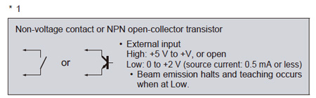
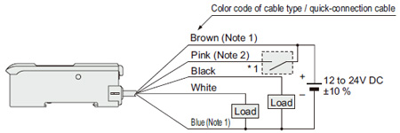
Wiring diagram
Notes:
| 1) |
The quick-connection sub cable does not have brown lead wire and blue lead wire.
The power is supplied from the connector of the main cable. |
| 2) |
The quick-connection cable does not have a pink lead wire. |
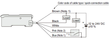
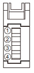
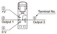
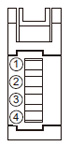
Terminal layout of connector type
* Connector for amplifier (CN-EP1) pin position
|
|
| Terminal No. |
Connection cable |
| ① |
Conductor core wire: Brown |
Cable color: Gray |
| ② |
Shield wire |
| ③ |
Conductor core wire: Yellow |
Cable color: Black |
| ④ |
Shield wire |
|
PNP output type
I/O circuit diagram
Notes:
| 1) |
The quick-connection sub cable does not have +V (brown) and 0 V (blue).
The power is supplied from the connector of the main cable. |
| 2) |
Connector type LS-401P does not incorporate the external input. |
| 3) |
LS-401P is 50 mA max. if 5 to 8 amplifiers are connected in cascade, and 25 mA max. if 9 to 16 amplifiers are connected in cascade. |
| Symbols・・・ |
D: Reverse supply polarity protection diode
ZD1, ZD2: Surge absorption zener diode
Tr1, Tr2: PNP output transistor |
Wiring diagram
Notes:
| 1) |
The quick-connection sub cable does not have brown lead wire and blue lead wire.
The power is supplied from the connector of the main cable. |
| 2) |
The quick-connection cable does not have a pink lead wire. |
Terminal layout of connector type
* Connector for amplifier (CN-EP1) pin position
|
|
| Terminal No. |
Connection cable |
| ① |
Conductor core wire: Brown |
Cable color: Gray |
| ② |
Shield wire |
| ③ |
Conductor core wire: Yellow |
Cable color: Black |
| ④ |
Shield wire |
|
Return to top
Return to top

 Business
> Industrial Devices
> Automation Controls Top
> FA Sensors & Components
> Sensors
> Photoelectric Sensors / Laser Sensors
> Digital Laser Sensor LS-400
> I/O Circuit and Wiring diagrams
Business
> Industrial Devices
> Automation Controls Top
> FA Sensors & Components
> Sensors
> Photoelectric Sensors / Laser Sensors
> Digital Laser Sensor LS-400
> I/O Circuit and Wiring diagrams