
 Business
> Industrial Devices
> Automation Controls Top
> FA Sensors & Components
> Sensors
> Photoelectric Sensors / Laser Sensors
> Digital Mark Sensor LX-100
> I/O Circuit and Wiring diagrams
Business
> Industrial Devices
> Automation Controls Top
> FA Sensors & Components
> Sensors
> Photoelectric Sensors / Laser Sensors
> Digital Mark Sensor LX-100
> I/O Circuit and Wiring diagrams
Digital Mark Sensor LX-100
I/O Circuit and Wiring diagrams
I/O circuit diagram
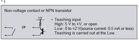
NPN output type
LX-101(-Z)
|
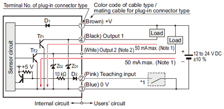
| Notes: | 1) The current of the plug-in connector type LX-101-Z is 100 mA max. 2) The output 2 is not incorporated to the plug-in connector type LX-101-Z. |
|---|
|
| Symbols・・・ | D1, D2 : Reverse supply polarity protection diode ZD1, ZD2: Surge absorption zener diode Tr1, Tr2 : NPN output transistor |
|---|
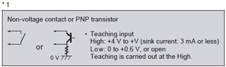
PNP output type
LX-101-P(-Z)
|
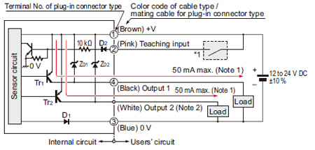
| Notes: | 1) The current of the plug-in connector type LX-101-P-Z is 100 mA max. 2) The output 2 is not incorporated to the plug-in connector type LX-101-P-Z. |
|---|
|
| Symbols・・・ | D1, D2 : Reverse supply polarity protection diode ZD1, ZD2: Surge absorption zener diode Tr1, Tr2 : PNP output transistor |
|---|
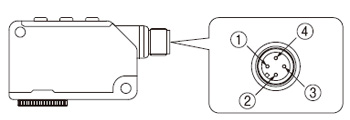
Connector pin layout of plug-in connector type
 |
|
CONTACT US
If you have any questions, please select the option below to contact us or find answers.
CONTACT US
BY EMAIL
BY EMAIL
Please click your area to select country or region


Related Information
Service & Support
Requests to customers (Automation Control Components & Industrial Device) [Excluding specific product]
Requests to customers (Automation Control Components & Industrial Device) [For specific product]
Requests to customers (FA Sensors & Components [Excluding motors])
Requests to customers (Dedicated to industrial motors)
- COMPONENTS & DEVICES
- FA SENSORS & COMPONENTS
- Fiber Sensors
- Photoelectric Sensors / Laser Sensors
- Micro Photoelectric Sensors
- Light Curtains / Safety Components
- Area Sensors
- Inductive Proximity Sensors
- Particular Use Sensors
- Sensor Options
- Wire-Saving Systems
- Programmable Controllers / Interface Terminal
- Human Machine Interface
- Pressure Sensors / Flow Sensors
- Measurement Sensors
- Static Control Devices
- Laser Markers / 2D Code Readers
- Machine Vision System
- Energy Management Solutions
- Timers / Counters / FA Components
- MOTORS
![]()