
 Business
> Industrial Devices
> Automation Controls Top
> FA Sensors & Components
> Sensors
> Inductive Proximity Sensors
> Rectangular-shaped Inductive Proximity Sensor GX-F/H
> Cautions For Use
Business
> Industrial Devices
> Automation Controls Top
> FA Sensors & Components
> Sensors
> Inductive Proximity Sensors
> Rectangular-shaped Inductive Proximity Sensor GX-F/H
> Cautions For Use
Rectangular-shaped Inductive Proximity Sensor GX-F/H
|
Cautions For Use
- Never use this product as a sensing device for personnel protection.
- In case of using sensing devices for personnel protection, use products which meet laws and standards, such as OSHA, ANSI or IEC etc., for personnel protection applicable in each region or country.
Mounting
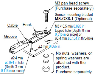
| GX-6 type |
- Use the optional sensor mounting bracket when installing.
<When using MS-GX6-1 (Optional / recommended)>
|
 |
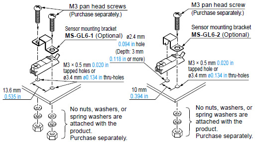
<When using MS-GL6-1(Optional) /MS-GL6-2 (Optional)>
- To mount the sensor with a nut, the mounting hole diameter should be ø3.4 mm ø0.134 in.
|
| GX-8 type |
<When using MS-GXL8-4 (Optional)>
|
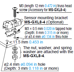 Note:Do not use a spring washer between the mounting screw and product. |
| GX-12 type |
|
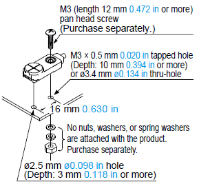 Note:Do not use a spring washer between the mounting screw and product. |
| GX-15 type |
|
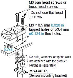 Note:Do not use a spring washer between the mounting screw and product. |
- When installing the long sensing range type on iron or stainless steel plate, put the optional aluminum sheet in between the sensor and the plate.
|
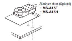 |
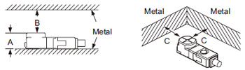
Influence of surrounding metal
- When there is a metal near the sensor, keep the minimum separation distance specified below.
| Front sensing type |
|
| GX-F6 type | GX-F8 type | GX-F12 type | GX-F15 type | GX-FL15 type | |
|---|---|---|---|---|---|
| A | 6 mm 0.236 in (Note 1) |
7.4 mm 0.291 in | 7.1 mm 0.280 in | 8 mm 0.315 in | 8 mm 0.315 in (Note 2) |
| B | 8 mm 0.315 in | 8 mm 0.315 in | 20 mm 0.787 in | 20 mm 0.787 in | 30 mm 1.181 in |
| C | 3 mm 0.118 in | 3 mm 0.118 in | 7 mm 0.276 in | 7 mm 0.276 in | 10 mm 0.394 in |
Notes:
| 1) | When using MS-GX6-1 (recommended mounting bracket, optional), the distance “A” including the thickness of mounting bracket will be 6.4 mm 0.252 in. |
|---|---|
| 2) | The GXL-FL15 type should be mounted on an insulator. To mount it on an iron or stainless steel, use the enclosed aluminum sheet. |
| Top sensing type |
|
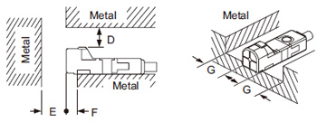
| GX-H6 type | GX-H8 type | GX-H12 type | GX-H15 type | GX-HL15 type | |
|---|---|---|---|---|---|
| D | 3 mm 0.118 in | 4 mm 0.157 in | 7 mm 0.276 in | 6 mm 0.236 in | 12 mm 0.472 in |
| E | 10 mm 0.394 in | 10 mm 0.394 in | 20 mm 0.787 in | 20 mm 0.787 in | 30 mm 1.181 in |
| F | 2 mm 0.079 in | 3 mm 0.118 in | 3 mm 0.118 in | 0 mm 0 in | 10 mm 0.394 in (Note) |
| G | 2 mm 0.079 in | 3 mm 0.118 in | 3 mm 0.118 in | 3 mm 0.118 in | 10 mm 0.394 in |
| Note: | When GX-HL15 type is mounted on an insulator or seated on the enclosed aluminum sheet, the distance “F” can be zero. |
|---|
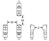
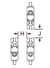
Mutual interference prevention
- When two or more sensors are installed in parallel or face to face, keep the minimum separation distance specified below to avoid mutual interference.
|
|
|||||||||||||||||||||||||||||||||||||||||
|
||||||||||||||||||||||||||||||||||||||||||
Notes:
| 1) | “I” in the model No. specifies the different frequency type. |
|---|---|
| 2) | Close mounting is possible for up to two sensors. When mounting three sensors or more at an equal spacing, align the model with “I” and the model without “I” alternately. The minimum value of dimension “H” should be as given below. GX-F6 / H6 type: 3.5mm 0.138 in GX-F8 / H8 type: 6mm 0.236 in GX-F12 / H12 type: 6.5mm 0.256 in GX-F15 / H15 type: 15mm 0.591 in GX-FL15 / HL15 type: 47.5mm 1.870 in |
Sensing range
- The sensing range is specified for the standard sensing object. With a non-ferrous metal, the sensing range is obtained by multiplying with the correction coefficient specified below. Further, the sensing range also changes if the sensing object is smaller than the standard sensing object or if the sensing object is plated.
Correction coefficient
| GX-F6 GX-H6 type |
GX-F8 GX-H8 type |
GX-F12 GX-H12 type |
GX-F15 GX-H15 type |
GX-FL15 type |
GX-HL15 type |
|
|---|---|---|---|---|---|---|
| Iron | 1 | 1 | 1 | 1 | 1 | 1 |
| Stainless steel (SUS304) |
0.76 approx. | 0.76 approx. | 0.79 approx. | 0.68 approx. | 0.70 approx. | 0.76 approx. |
| Brass | 0.50 approx. | 0.50 approx. | 0.56 approx. | 0.47 approx. | 0.45 approx. | 0.50 approx. |
| Aluminum | 0.48 approx. | 0.48 approx. | 0.53 approx. | 0.45 approx. | 0.43 approx. | 0.48 approx. |
Wiring
- The output does not incorporate a short-circuit protection circuit. Do not connect it directly to a power supply or a capacitive load.
Others
- Do not use during the initial transient time (50 ms) after the power supply is switched on.
BY EMAIL


Requests to customers (Automation Control Components & Industrial Device) [Excluding specific product]
Requests to customers (Automation Control Components & Industrial Device) [For specific product]
Requests to customers (FA Sensors & Components [Excluding motors])
Requests to customers (Dedicated to industrial motors)
- COMPONENTS & DEVICES
- FA SENSORS & COMPONENTS
- Fiber Sensors
- Photoelectric Sensors / Laser Sensors
- Micro Photoelectric Sensors
- Light Curtains / Safety Components
- Area Sensors
- Inductive Proximity Sensors
- Particular Use Sensors
- Sensor Options
- Wire-Saving Systems
- Programmable Controllers / Interface Terminal
- Human Machine Interface
- Pressure Sensors / Flow Sensors
- Measurement Sensors
- Static Control Devices
- Laser Markers / 2D Code Readers
- Machine Vision System
- Energy Management Solutions
- Timers / Counters / FA Components
- MOTORS
![]()