Micro-size Inductive Proximity Sensor GXL (Discontinued Products)
We are sorry, the products have been discontinued. Please refer to the details of the discontinued products and the recommended substitutes list below.
 |
September 30, 2022 |
|
|
I/O Circuit and Wiring diagrams
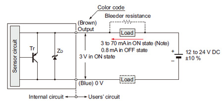
GXL-8 type
I/O circuit diagram
| Symbols・・・ |
ZD: Surge absorption zener diode
Tr : PNP output transistor |
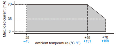
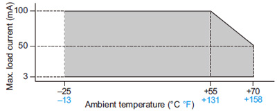
| Note: |
The maximum load current varies depending on the ambient temperature. |
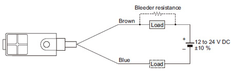
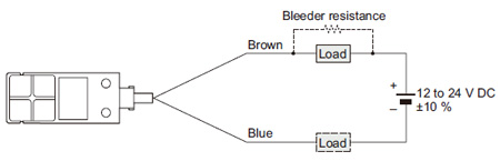
Wiring diagram
Conditions for the load
| 1) |
The load should not be actuated by the leakage current (0.8 mA) in the OFF state. |
| 2) |
The load should be actuated by (supply voltage – 3 V) in the ON state. |
| 3) |
The current in the ON state should be between 3 to 70 mA DC.
[In case the current is less than 3 mA, connect a bleeder resistance in parallel to the load so that a current of 3 mA, or more, flows.] |
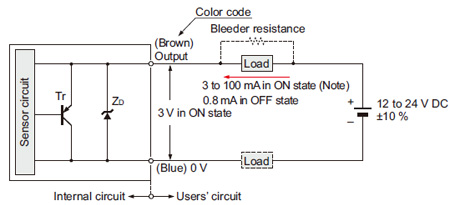
GXL-15 type
I/O circuit diagram
| Symbols・・・ |
ZD: Surge absorption zener diode
Tr : PNP output transistor |
| Note: |
The maximum load current varies depending on the ambient temperature. |
Wiring diagram
Conditions for the load
| 1) |
The load should not be actuated by the leakage current (0.8 mA) in the OFF state. |
| 2) |
The load should be actuated by (supply voltage – 3 V) in the ON state. |
| 3) |
The current in the ON state should be between 3 to 100 mA DC.
[In case the current is less than 3 mA, connect a bleeder resistance in parallel to the load so that a current of 3 mA, or more, flows.] |
Return to top
Return to top

 Business
> Industrial Devices
> Automation Controls Top
> FA Sensors & Components
> Sensors
> Inductive Proximity Sensors
> Micro-size Inductive Proximity Sensor GXL(Discontinued Products)
> I/O Circuit and Wiring diagrams
Business
> Industrial Devices
> Automation Controls Top
> FA Sensors & Components
> Sensors
> Inductive Proximity Sensors
> Micro-size Inductive Proximity Sensor GXL(Discontinued Products)
> I/O Circuit and Wiring diagrams