
 Business
> Industrial Devices
> Automation Controls Top
> FA Sensors & Components
> Sensors
> Light Curtains / Safety Components
> Safety Light Curtain Type 2 SF2B Ver.2(Discontinued Products)
> Cautions For Use
Business
> Industrial Devices
> Automation Controls Top
> FA Sensors & Components
> Sensors
> Light Curtains / Safety Components
> Safety Light Curtain Type 2 SF2B Ver.2(Discontinued Products)
> Cautions For Use
Safety Light Curtain Type 2 SF2B Ver.2 (Discontinued Products)
|
We are sorry, the products have been discontinued. Please refer to the details of the discontinued products and the recommended substitutes list below.
|
Cautions For Use
- This safety light curtain is a Type 2 electrosensitive protective equipment. It is specified that this safety light curtain be utilized only within systems implementing control categories 2, 1 and B (safety-related categories for control systems), as determined by ISO 13849-1. This safety light curtain must never be utilized in any system that requires the usage of category 4 equipment, such as press machines; nor for systems requiring category 3 equipment.
- To use this product in the U.S.A., refer to OSHA 1910.212 and OSHA 1910.217 for installation, and in Europe, refer to EN ISO 13855 as well. Observe your national and local requirements before installing this product.
| ・ | This catalog is a guide to select a suitable product. Be sure to read instruction manual prior to its use. |
|---|---|
| ・ | Both emitter and receiver are adjusted before shipment, please apply both emitter and receiver with the same serial No. The serial No. is indicated on the plates of both emitter and receiver. (Indicated under the model No.) |
- Make sure to carry out the test run before regular operation.
- This safety system is for use only on machinery in which the dangerous parts can be stopped immediately, either by an emergency stop unit or by disconnecting the power supply. Do not use this system with machinery which cannot be stopped at any point in its operation cycle.
Self-diagnosis function
- This safety light curtain incorporates the self-diagnosis function. In case an abnormality is detected during self-diagnosis, the safety light curtain is put in the lockout state at that instant, and the control output (OSSD 1, OSSD 2) is fixed at the OFF state. Refer to “Troubleshooting” and the instruction manual and remove the cause of the abnormality.
- In order to maintain safe condition of safety light curtain, inspect the beam interrupted status of the device once a day or more. Failure to do so could delay the detection of unexpected abnormality and increase the degree of hazard, which may cause the malfunction of safety light curtain, resulting in serious body injury or death.
- In order to check all abnormalities in the OSSD 1, OSSD 2 and auxiliary output, the beam interrupted status of device must be checked. Perform either of two below to inspect the device under beam interrupted status.
- Emission halt by test input (Emission halt function)
- Beam interrupting by test rod (Excluding the cable SF2B-CB05-A)
・ Emission halt by test input (Emission halt function) ・ Beam interrupting by test rod
(Excluding the cable SF2B-CB05-A)
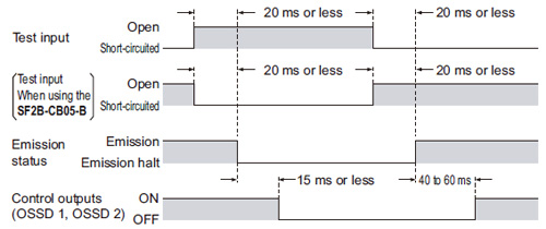
Emission halt function (Test input)
- This function stops the emission process of the emitter. You can select whether emission is on or halted by means of the connection status for the test input (pink).
| Test input | Emission status | |
|---|---|---|
| When using the |
||
| Open | Emission halt | Emission |
| Connected to 0 V or +V | Emission | Emission halt |
- During emission halt, the control outputs (OSSD 1, OSSD 2) become OFF status.
- By using this function, malfunction due to extraneous noise or abnormality in the control outputs (OSSD 1, OSSD 2) and the auxiliary output can be determined even from the machinery side.
<Time chart>
|
- Do not use the emission halt function (test input) for the purpose of stopping the device. Failure to do so could result in serious injury or death.
Auxiliary output
- Auxiliary output is incorporated into the emitter and its operation varies depending on the type of bottom cap cable (optional) to be used.
| Bottom cap cable | Normal mode | Lockout | ||
|---|---|---|---|---|
| Emission halt | Control outputs (OSSD 1, OSSD 2) status |
|||
| Beam received | Beam interrupted | |||
| When using the SF2B-CCB□ / SF2B-CB□ |
ON | OFF | ON | ON |
| When using the SF2B-CB05-A |
OFF | ON | ON | OFF |
| SF2B-CB05-B | Cannot be used. | |||
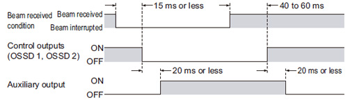
| When bottom cap cable SF2B-CCB□ or SF2B-CB□ (optional) is used |
- The auxiliary output is incorporated in the emitter. It is OFF when the control outputs (OSSD 1,OSSD 2) are ON and vice versa.
- The auxiliary output can be used as an operation monitor of the device.
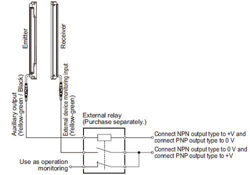
- When the external device monitor function is not used, connect the external device monitor input line to the auxiliary output line to disable the function.
In this case, do not connect the load to the auxiliary output. For details, refer to “External device monitoring function” and “I/O CIRCUIT AND WIRING DIAGRAMS”. - When the external device monitoring function is used to disable, do not directly use the auxiliary output as the operation monitor of this safety light curtain. When the external device monitor is used to disable and the auxiliary output is used to monitor the operation of safety light curtain, connect the auxiliary output and the external device monitoring input to the external relay (purchase separately) to use the external relay contacting point as an operation monitor of this safety light curtain.
|
|
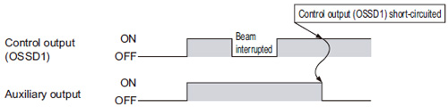
| When bottom cap cable SF2B-CB05-A (optional) is used |
- Make sure to use the auxiliary output when using the bottom cap cable SF2B-CB05-A (optional). Set the device so the control machine can be stopped when either the control output (OSSD 1) or auxiliary output turns to OFF. If the auxiliary output is should not be used, the device cannot stop operation when an unexpected error occurs during control output (OSSD 1) failure, which may result in serious injury or death.
- The auxiliary output is incorporated in the emitter. It outputs ON at the normal operation of device. It outputs OFF in the following cases:
・ When an abnormality which needs emission halt status occurs [for example, the control output (OSSD 1) short-circuit and an error occurs.] ・ While test input has been input - The error cannot be transmitted to the control machine. The alarm signal is output from the auxiliary output.
|
| When bottom cap cable SF2B-CB05-B (optional) is used |
- The auxiliary output cannot be utilized by using the bottom cap cable SF2B-CB05-B (optional).
External device monitoring function
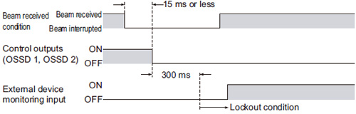
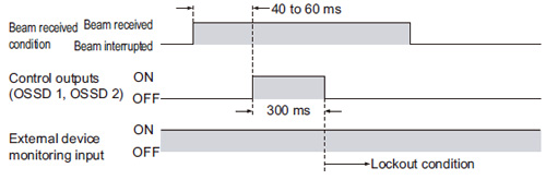
- This function is available when the bottom cap cable SF2B-CCB□ or SF2B-CB□ (optional) is used. This is the function for checking whether the external safety relay connected to the control outputs (OSSD 1, OSSD 2) performs normally in accordance with the control outputs (OSSD 1, OSSD 2) or not. Monitor the b contact of the external safety relay, and if any abnormality such as deposit of the contacting point, etc. is detected, change the status of the safety light curtain into lockout one, and turn OFF the control outputs (OSSD 1, OSSD 2).
| In case of setting the external device monitoring function to enabled |
- Connect the external device monitoring input (yellow-green) to the b contact of the external safety relay that is connected to the control outputs (OSSD 1, OSSD 2).
| In case of not using the external device monitoring function |
- Connect the external device monitoring input (yellow-green) to the auxiliary output (yellow-green / black).
|
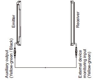
|
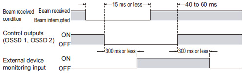
- The time set for external device monitoring is 300 ms or less. Exceeding 300 ms turns the safety light curtain into lockout condition.
|
|
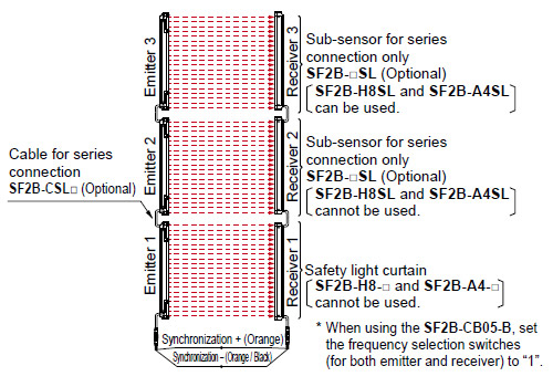
Series connection
| Connectable up to 3 sets of safety light curtains (however, 128 beam channels max.) (Note 1, 2) |
- This is the configuration for connecting multiple sets of emitters and receivers facing each other in series. It is used when the dangerous part can be entered from two or more directions. The control outputs (OSSD 1, OSSD 2) turns OFF if any of the safety light curtain is interrupted. For details, refer to the instruction manual.
Notes:
| 1): | Series connection connectors cannot be used with the SF2B-H8-□ and SF2B-A4-□, and so series connection is not possible. The SF2B-H8SL and SF2B-A4SL are not equipped with series connection connectors, so when connecting three sets in series, they cannot be used in the middle position. | ||
|---|---|---|---|
| 2): | The total number of beam axes for the SF2B-A□ is a maximum of 96 when two sets are connected, and 64 when three sets are connected. When SF2B-H□ and SF2B-A□ are combined in series connection, double the number of the beam channels of SF2B-A□ to calculate the total number of beam channels, which should be 128 or less.
|
- For serial connections, connect the emitter and receiver of the safety light curtain to the emitter and receiver respectively of the sub-sensors for series connection using the SF2B-CSL□ special series connection cables. Wrong connection could generate the non-sensing area, resulting in serious injury or death.
|
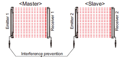
Parallel connection
- Up to a maximum of two sets can be connected in parallel only when using the SF2B-CB05-B adapter cable (optional). For details, refer to the instruction manual.
|
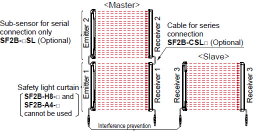
Series and parallel mixed connection
- Up to a maximum of three sets can be connected in a mixture of series and parallel (for a total maximum number of 128 beam channels. However, the total number of beam channels for the SF2B-A□ is a maximum of 96 when two sets are connected, and 64 when three sets are connected.) only when using the SF2B-CB05-B adapter cable (optional). For details, refer to the instruction manual.
|
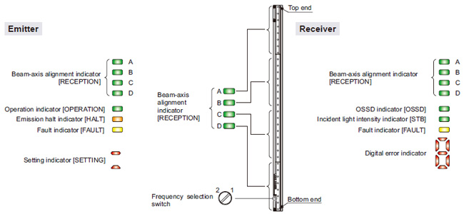
Part description and function
|
|
|
|||||||||||||||||||||||||||||||||||||||||||||||||||||||
Notes:
| 1) | The threshold value where the control output changes from OFF to ON is applied as “100 % incident light intensity”. |
|---|---|
| 2) | The status “when light is interrupted” refers to the status that the some obstacle is existed in the sensing area. |
| 3) | For details, refer to “Troubleshooting” and the SF2B instruction manual. |
| 4) | The description given in [ ] is marked on the safety light curtain. |
Wiring
- Refer to the applicable regulations for the region where this safety light curtain is to be used when setting up the safety light curtain. In addition, make sure that all necessary measures are taken to prevent possible dangerous operating errors resulting from earth faults.
- Make sure to carry out the wiring in the power supply off condition.
- Verify that the supply voltage variation is within the rating.
- If power is supplied from a commercial switching regulator, ensure that the frame ground (F.G.) terminal of the power supply is connected to an actual ground.
- In case noise generating equipment (switching regulator, inverter motor, etc.) is used in the vicinity of this sensor, connect the frame ground (F.G.) terminal of the equipment to an actual ground.
- Do not run the wires together with high-voltage lines or power lines or put them in the same raceway. This can cause malfunction due to induction.
Others
- This device has been developed / produced for industrial use only.
- Do not use during the initial transient time (2 s) after the power supply is switched on.
- Avoid dust, dirt and steam.
- Take care that the sensor does not come in direct contact with water, oil, grease, or organic solvents, such as, thinner, etc.
- Take care that the sensor is not directly exposed to fluorescent light from a rapid-starter lamp or a high frequency lighting device, as it may affect the sensing performance.
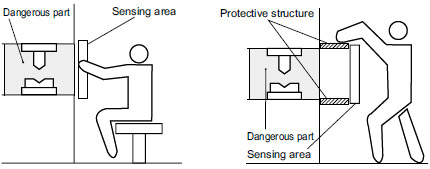
Sensing area
- Make sure to install this product such that any part of the human body must pass through its sensing area in order to reach the dangerous parts of the machinery. If the human body is not detected, there is a danger of serious injury or death.
- Do not use any reflective type or retroreflective type arrangement.
- Emitter and receiver that face each other should be from the same model No. (with same beam axis pitch and number of beam channels) and aligned in the vertical direction. If units from different sets are connected together, it may cause blind spots in the sensing area, and death or serious injury may result.
- Do not connect facing several receivers towards one emitter.
|
|
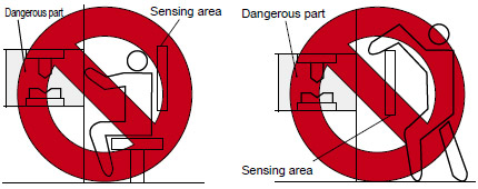
Safety distance
- Calculate the safety distance correctly, and always maintain a distance which is equal to or greater than the safety distance, between the sensing area of this safety light curtain and the dangerous parts of the machinery. (Please check the latest standards for the equation.) If the safety distance is miscalculated or if sufficient distance is not maintained, there is a danger of serious injury or death.
- Before designing the system, refer to the relevant standards of the region where this device is to be used and then install this device.
|
- Safety distance is calculated based on the following equation when a person moves perpendicular (normal intrusion) to the sensing area of the safety light curtain. In case the intrusion direction is not perpendicular to the sensing area, be sure to refer to the relevant standard (regional standard, specification of the machine, etc.) for details of the calculation. (Please check the latest standards for the equation.)
| For use based on EN ISO 13855 / ISO 13855 / JIS B 9715 |
For intrusion direction perpendicular to the sensing area
- Equation 1 S = K × T + C
S: Safety distance (mm)
Minimum required distance between the sensing area surface and the dangerous parts of the machineK: Intrusion speed of operator’s body or objects (mm/sec.)
Normally, taken as SF2B-H□ 2,000 (mm/sec.),
SF2B-A□ 1,600 (mm/sec.) for calculation.T: Response time of total equipment (sec.)
T = Tm + TSF2B
Tm: Maximum halting time of machinery (sec.)
TSF2B: Response time of the SF2B series 0.015 (sec.)C: Additional distance calculated from the size of the minimum sensing object of the safety light curtain (mm)
However, the value of “C” cannot be 0 or less.
C = 8 × (d – 14)
For SF2B-A□, C = 850 (mm) 33.465 (in) (constant)d: Minimum sensing object diameter
SF2B-H□: d= 27 (mm) 1.063 (in), C = 104 (mm) 4.094 (in)
| ・ | For calculating the safety distance “S”, there are the following five cases. First calculate by substituting the value K = 2,000 (mm/sec.) in the equation above. Then, classify the obtained value of “S” into three cases, 1) S < 100, 2) 100 ≤ S ≤ 500, and 3) S > 500. For Case 3) S > 500, recalculate by substituting the value K = 1,600 (mm/sec.). After that, classify the calculation result into two cases, 4) S ≤ 500 and 5) S > 500. For details, refer to the instruction manual enclosed with this product. |
|---|
| For use based on ANSI B11.19 |
- Equation 2 S = K × (Ts + Tc + TSF2B + Tbm) + Dpf
S: Safety distance (mm)
Minimum required distance between the sensing area surface and the dangerous parts of the machineK: Intrusion velocity {Recommended value in OSHA is 63 (inch/sec.)
≈ 1,600 (mm/sec.)}
ANSI B11.19 does not define the intrusion velocity “K”. When determining K,
consider possible factors including physical ability of operators.Ts: Halting time calculated from the operation time of the control element (air valve, etc.) (sec.) Tc: Maximum response time of the control circuit required for functioning the brake (sec.) TSF2B: Response time of safety light curtain 0.015 (sec.) Tbm: Additional halting time tolerance for the brake monitor (sec.)
Tbm = Ta – (Ts + Tc)
Ta: Setting time of brake monitor (sec.)
When the machine is not equipped with a brake monitor, it is recommended
that 20 % or more of
(Ts + Tc) is taken as additional halting time.Dpf: Additional distance calculated from the size of the minimum sensing object of the safety light curtain
SF2B-H□ Dpf = 2.676 (inch) ≈ 68 (mm)
SF2B-A□ Dpf = 5.355 (inch) ≈ 136 (mm)
Dpf = 3.4 × (d – 0.276) (inch)
Dpf ≈ 3.4 × (d – 7) (mm)
d: Minimum sensing object diameter 1.063 (inch) ≈ 27 (mm) SF2B-H□
Minimum sensing object diameter 1.851 (inch) ≈ 47 (mm) SF2B-A□
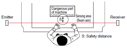
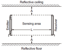
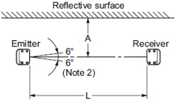
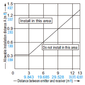
Influence of reflective surfaces
- Install the safety light curtain by considering the effect of nearby reflective surfaces, and take countermeasures such as painting, masking, or changing the material of the reflective surface, etc. Failure to do so may cause the safety light curtain not to detect, resulting in serious body injury or death.
- Keep the minimum distance given below, between the safety light curtain and a reflective surface.
|
|
Notes:
| 1) | If using the SF2B-CB05-B, the operating range is 0.3 to 5 m 0.984 to 16.404 ft. |
|---|---|
| 2) | The effective aperture angle for this device is ±5°or less (when L > 3 m 9.843 ft) as required by IEC 61496-2 / UL 61496-2. However, install this device away from reflective surfaces considering an effective aperture angle of ±6° to take care of beam misalignment, etc. during installation. |
Troubleshooting
| Emitter side |
| Phenomenon | Cause | Remedy |
|---|---|---|
| All indicators are off. | Power is not being supplied. | Check that the power supply capacity is sufficient. Connect the power supply correctly. |
| Supply voltage is out of the specified range. | Provide the supply voltage within the specified range. | |
| Connector is not connected securely. | Connect the connector securely. | |
| Operation indicator remains lit up in red (beam is not received). [OPERATION]  |
The beam channels of the emitter and the receiver are not correctly aligned. | Align the beam channels. |
| Emission halt indicator (orange) lights up. [HALT]  |
Emission is in halt condition. | Connect the test input (emission halt input) wire correctly. The logic varies depending on the cable to be used. |
| The synchronization wire error | Connect the synchronization wire correctly. | |
| The receiver does not work. | Check the operation of the receiver side. | |
| The interference prevention wire error (When using the SF2B-CB05-B: When set to slave) |
Connect the interference prevention wire correctly. | |
| Master / slave setting error (When using the SF2B-CB05-B: When set to master) |
Set the master / slave setting to “master”. | |
| The master sensor does not work. | Check the master side safety light curtain. | |
| Fault indicator (yellow) lights up or blinks. [FAULT]  |
[Blinks once] Total safety light curtains No. / total beam channel No. error |
Connect the end cap properly. Connect the cable for series connection correctly. Check the model (emitter / receiver) of sub-sensor for series connection. Set the No. of the safety light curtains in series connection, and a total No. of beam channels within the specification. |
| [Blinks twice] Auxiliary output error |
Connect the auxiliary output cable correctly. | |
| [Other than the above] Effect from noise / power supply or failure of internal circuit |
Check the noise status around this safety light curtains. Check the wiring, supplied voltage and power supply capacity. Even if the error is not eliminated, contact our office. |
| Receiver side |
| Phenomenon | Cause | Remedy |
|---|---|---|
| All indicators are off. | Power is not being supplied. | Check that the power supply capacity is sufficient. Connect the power supply correctly. |
| Supply voltage is output of the specified range. | Set the supply voltage correctly. | |
| Connector is not connected securely. | Connect the connector securely. | |
| OSSD indicator remains lit up in red (beam is not received). [OSSD] |
The beam channels of the emitter and the receiver are not correctly aligned. | Align the beam channels. |
| Total unit No. / total beam channel No. error | Set the same value to the Nos. of emitter and receiver. | |
| The master / slave setting is different. (When using with the SF2B-CB05-B) |
Set the setting identically. | |
| Stable indicator lights up (Orange) [STB] |
The beam channels of the emitter and the receiver are not correctly aligned. | Align the beam channels. |
| Fault indicator (yellow) lights up or blinks. [FAULT] |
[Digital error indicator 1 ] Total safety light curtain No. / total beam channel No. error |
Connect the end cap properly. Connect the cable for series connection correctly. Check the model (emitter / receiver) of sub sensor for series connection. Check that the number of safety light curtains / number of beam axes is within the specification value. |
| [Digital error indicator 2 ] Control outputs (OSSD 1, OSSD 2) error |
Connect the control outputs (OSSD1, OSSD2) correctly. | |
| [Digital error indicator 4 ] Extraneous light error |
Prevent any extraneous light from entering the receiver. | |
| [Digital error indicator 7 ] External device monitoring error |
Connect the external device monitor input wire correctly. Replace the replay unit. Replace the relay unit having appropriate response time. |
|
| [Digital error indicator 6 ] Bottom connector error |
Check the type of the bottom connector. Cable of the emitter: Gray (with black stripe) |
|
| [Other than the above] Effect from noise / power supply or failure of internal circuit |
Check the noise status around this safety light curtain. Check the wiring, supplied voltage and power supply capacity. Even if the error is not eliminated, contact our office. |
Corner mirror
- Be sure to carry out maintenance while referring to the instruction manual for the SF4B / SF2B series of safety light curtains.
- Do not use if dirt, water, or oil, etc. is attached to the reflective surface of this product. Appropriate sensing range may not be maintained due to diffusion or refraction.
- Make sure that you have read the instruction manual for the corner mirror thoroughly before setting up the corner mirrors and safety light curtains, and follow the instructions given. If the equipment is not set up correctly as stipulated in the instruction manual, incident light errors may result in unexpected situations which may result in serious injury or death.
- Please download the instruction manuals from our website.
- Safety light curtain SF4B / SF2B series cannot be used as a retroreflective type. Avoid installing the safety light curtain as a retroreflective type when this product is applied.
- The mirror part of this product is made of glass. Note that if it is broken, the glass shards may fly apart.
BY EMAIL


Requests to customers (Automation Control Components & Industrial Device) [Excluding specific product]
Requests to customers (Automation Control Components & Industrial Device) [For specific product]
Requests to customers (FA Sensors & Components [Excluding motors])
Requests to customers (Dedicated to industrial motors)
- COMPONENTS & DEVICES
- FA SENSORS & COMPONENTS
- Fiber Sensors
- Photoelectric Sensors / Laser Sensors
- Micro Photoelectric Sensors
- Light Curtains / Safety Components
- Area Sensors
- Inductive Proximity Sensors
- Particular Use Sensors
- Sensor Options
- Wire-Saving Systems
- Programmable Controllers / Interface Terminal
- Human Machine Interface
- Pressure Sensors / Flow Sensors
- Measurement Sensors
- Static Control Devices
- Laser Markers / 2D Code Readers
- Machine Vision System
- Energy Management Solutions
- Timers / Counters / FA Components
- MOTORS
![]()