
 Business
> Industrial Devices
> Automation Controls Top
> FA Sensors & Components
> Static Control Devices
> Static Control Devices
> Electrostatic Sensor EF-S1
> I/O Circuit and Wiring diagrams
Business
> Industrial Devices
> Automation Controls Top
> FA Sensors & Components
> Static Control Devices
> Static Control Devices
> Electrostatic Sensor EF-S1
> I/O Circuit and Wiring diagrams
Electrostatic Sensor EF-S1
|
I/O Circuit and Wiring diagrams
EF-S1C[NPN output]
I/O circuit diagram
|
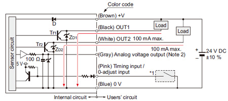
Notes:
| 1) | If using together with an ionizer, the 0 V line of this product should be connected to the ionizer ground. In addition, the metal parts of the sensor head (EF-S1HS) are connected to the 0 V line, so it should be insulated during installation. |
|---|---|
| 2) | In case of using the analog voltage output, connect a device having a input impedance of 1MΩ or more. Further, the analog voltage output does not incorporate a short-circuit protection circuit. Do not connect it directly to a power supply or a capacitive load. |
|
| Symbols・・・ | D : Reverse supply polarity protection diode ZD1, ZD2 : Surge absorption zener diode Tr1, Tr2 : NPN output transistor |
|---|
Wiring diagram
|
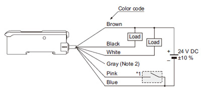
|
<Points to note when using analog output> Because the 0 V lines for judgment output and analog voltage output are common, the analog voltage output may vary depending on the load current. In order to satisfy the linearity specifications for the analog voltage output, do not use the judgment output. |
* Connector for controller (CN-EP1) pin position
|
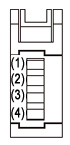
| Terminal No. | Mating cable |
|---|---|
| (1) | +V: Brown |
| (2) | 0 V: Blue |
| (3) | Sensor output: Orange / Violet |
| (4) | Shield wire |
CONTACT US
If you have any questions, please select the option below to contact us or find answers.
CONTACT US
BY EMAIL
BY EMAIL
Please click your area to select country or region


Related Information
Service & Support
Requests to customers (Automation Control Components & Industrial Device) [Excluding specific product]
Requests to customers (Automation Control Components & Industrial Device) [For specific product]
Requests to customers (FA Sensors & Components [Excluding motors])
Requests to customers (Dedicated to industrial motors)
- COMPONENTS & DEVICES
- FA SENSORS & COMPONENTS
- Fiber Sensors
- Photoelectric Sensors / Laser Sensors
- Micro Photoelectric Sensors
- Light Curtains / Safety Components
- Area Sensors
- Inductive Proximity Sensors
- Particular Use Sensors
- Sensor Options
- Wire-Saving Systems
- Programmable Controllers / Interface Terminal
- Human Machine Interface
- Pressure Sensors / Flow Sensors
- Measurement Sensors
- Static Control Devices
- Laser Markers / 2D Code Readers
- Machine Vision System
- Energy Management Solutions
- Timers / Counters / FA Components
- MOTORS
![]()