
 Business
> Industrial Devices
> Automation Controls Top
> FA Sensors & Components
> Motors for FA & Industrial Application
> AC Servo
>
> Wiring/ Connection
Business
> Industrial Devices
> Automation Controls Top
> FA Sensors & Components
> Motors for FA & Industrial Application
> AC Servo
>
> Wiring/ Connection
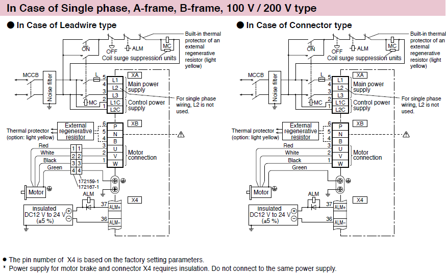
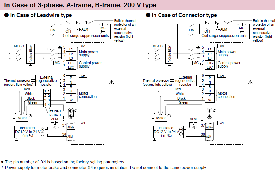
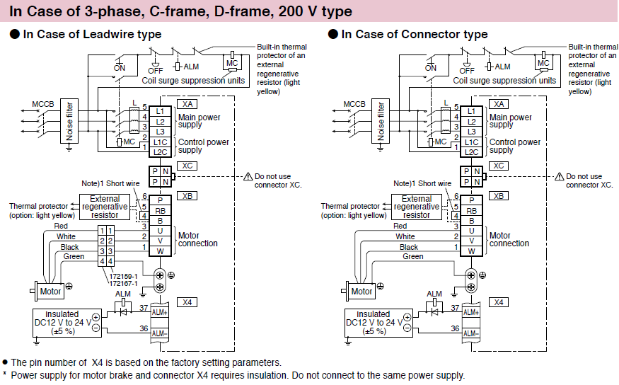
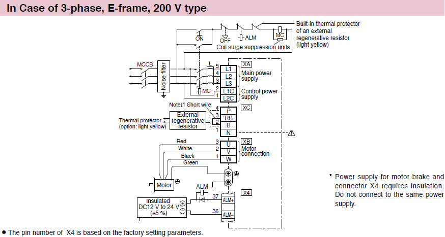
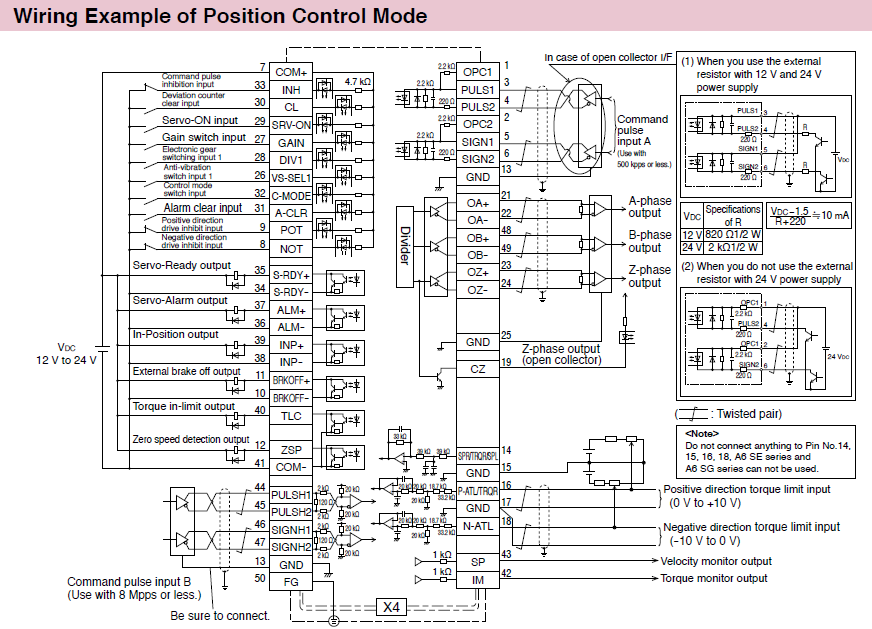
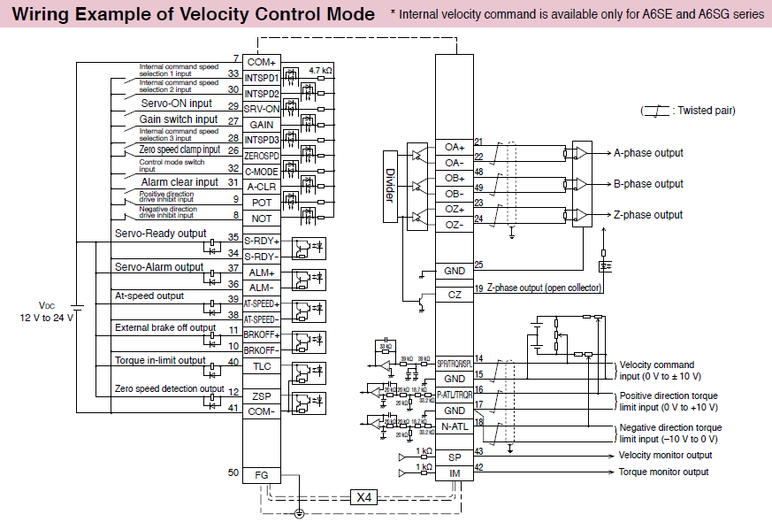
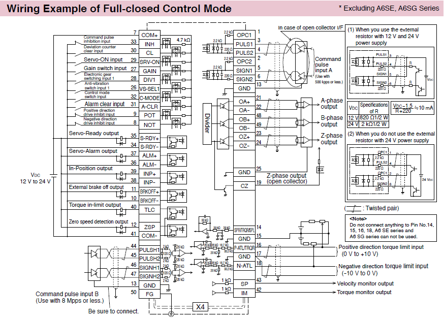
Wiring Diagram
Wiring to Connector, XA, XB, XC and Terminal Block
|
|
||||||||||||||
|

|
||||||||||||||
|
||||||||||||||
|
||||||||||||||

|
||||||||||||||
|
||||||||||||||
Safety Function
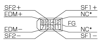
Wiring to the Connector, X3 * Excluding A6 SE, A6 SG Series
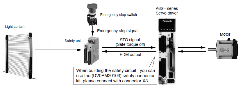
Connecting the host controller can configure a safety circuit that controls the safety functions.
When not constructing the safety circuit, use the supplied safety bypass plug.
Outline Description of Safe Torque Off (STO)
|
Safety Precautions
|
||||||||||||||||||||||||||||||
●System configuration
|
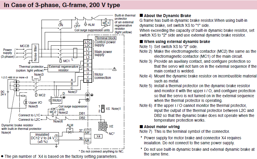
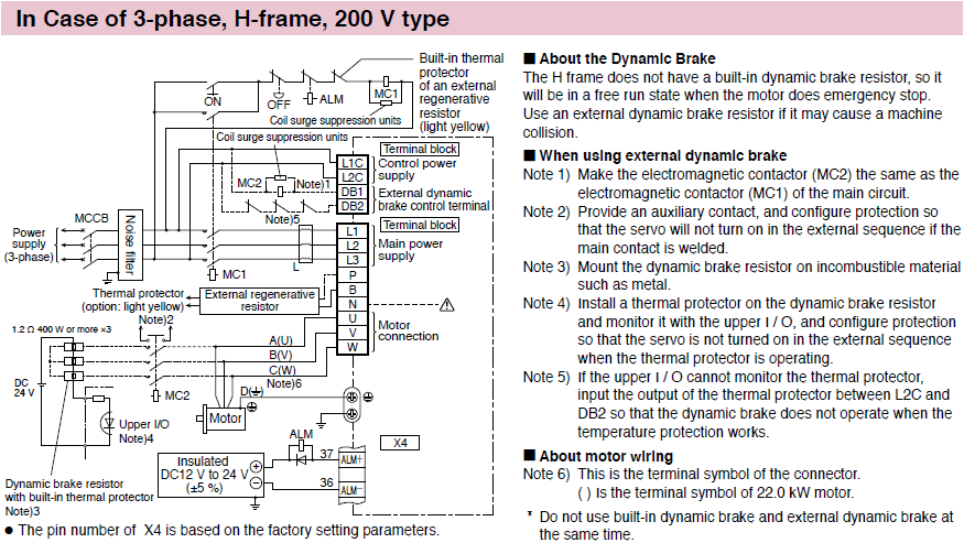
Control Circuit Diagram
Wiring to the Connector, X4
|
|
|

|
Wiring to the Connector, X5 * Excluding A6 SE, A6 SG Series
Applicable External Scale
| Scale Type | Partner | Series | Resolution*1 [μm] |
Max. rate*1 [m/s] |
|---|---|---|---|---|
Parallel Type (A/B/Z phase) |
General | — |
Maximum speed after4× multiplication :
4 Mpps |
|
Serial (Incremental) |
Magnescale Co., Ltd. | SL700+PL101RP/RHP |
0.1 |
10 |
SL710+PL101RP/RHP |
0.1 |
10 |
||
SR75/SR85 |
0.01 to 1 |
3.3 |
||
BF1 |
0.001/0.01 |
0.4/1.8 |
||
SQ10 |
0.05/0.1/0.5/1 |
3 |
||
| NIDEC MACHINE TOOL CORPORATION | MPLIN |
0.1 |
30 |
|
| Nidec Sankyo Corporation | PSLH041+PSLG |
0.1 |
6 |
|
Serial
(Absolute) |
FAGOR AUTOMATION | S3BP/G3BP |
0.01/0.05 |
3 |
LAP |
0.01/0.05 |
3 |
||
EXA/ EXG/ EXT |
0.01/0.05 |
8 |
||
H2AP-D200/H2AP-D90 |
29 bit/23 bit |
750 rpm/1500 rpm |
||
S2AP-D170,/S2AP-D90 |
23 bit |
1500 rpm |
||
| HEIDENHAIN | LIC 2197P/LIC 2199P |
0.05/0.1 |
10 |
|
LIC 4193P/LIC 4195P LIC 4197P/LIC 4199P |
0.001/0.005/0.01 |
10 |
||
LC 195P/LC 495P |
0.001/0.01 |
3 |
||
ECA 4490P |
27 bits to 29 bits |
7000 rpm〜550 rpm
(Depends on drum size) |
||
RCN 2x90P/RCN 5x90P |
26 bits/28 bits |
1500 rpm |
||
RCN 8x90P |
29 bit |
500 rpm |
||
| Magnescale Co.,Ltd. | SR77/SR87 |
0.01 to 1 |
3.3 |
|
| Mitutoyo Corporation | AT573-SC/H |
0.05 |
2.5 |
|
ST700 |
0.1 |
5 |
||
ST1300 |
0.001/0.01 |
8 |
||
| NIDEC MACHINE TOOL CORPORATION | MPZA/MPRZ |
23 bits |
10000 r/min, 5000 r/min |
|
| Renishaw plc | RESOLUTE |
0.001 |
4 |
|
0.05 |
100 |
|||
0.1 |
100 |
|||
| RSF Electronik | MC 15P MP/MC 15P MK |
0.05/0.1 |
10 |
|
MCR 15P |
22 bits〜25 bits |
— |
||
*1 The maximum speed is a characteristic of the driver. It is limited by the configration of the machine and the system.
* For more information about the external scale product, please contact the manufacturer.
|

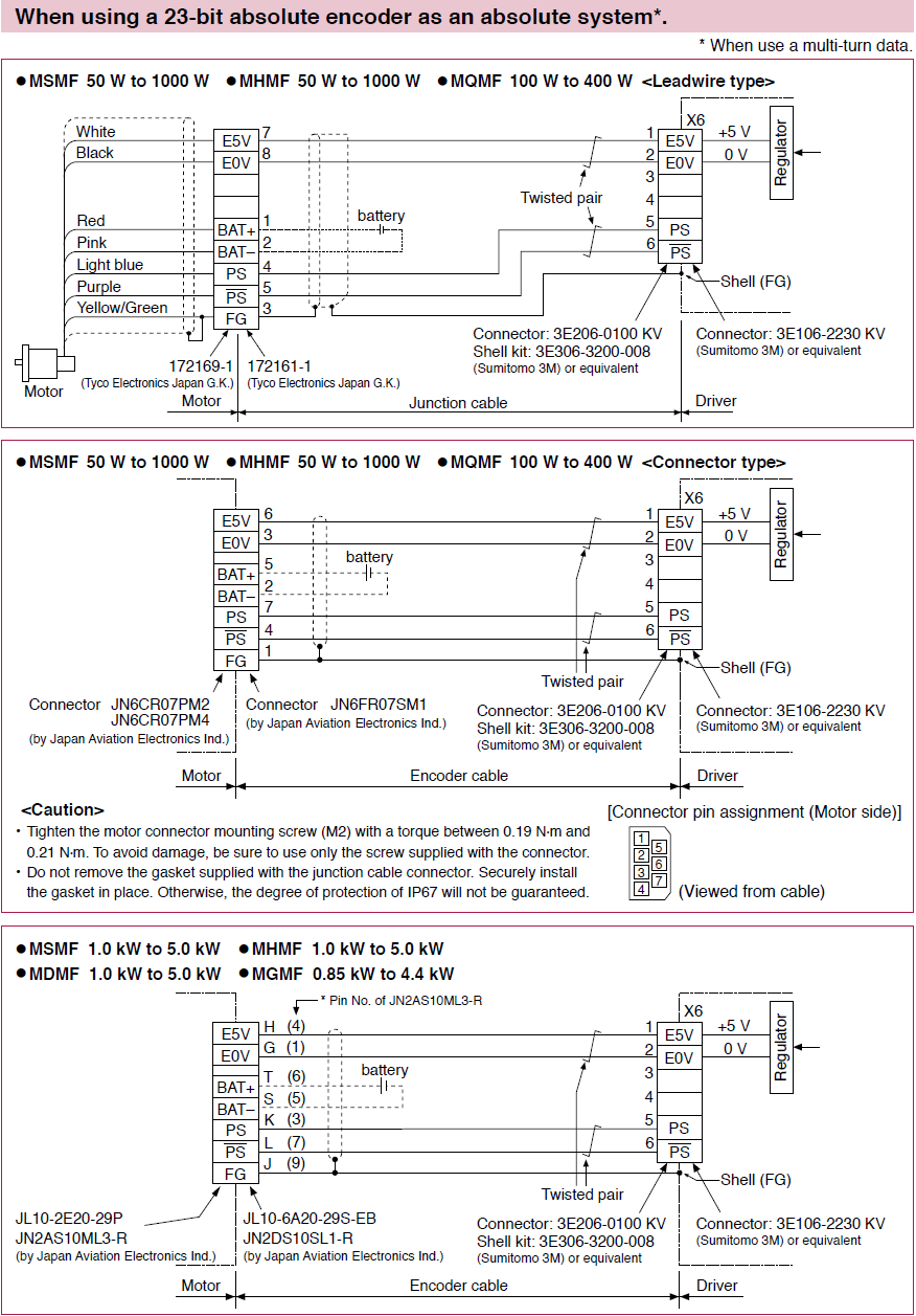
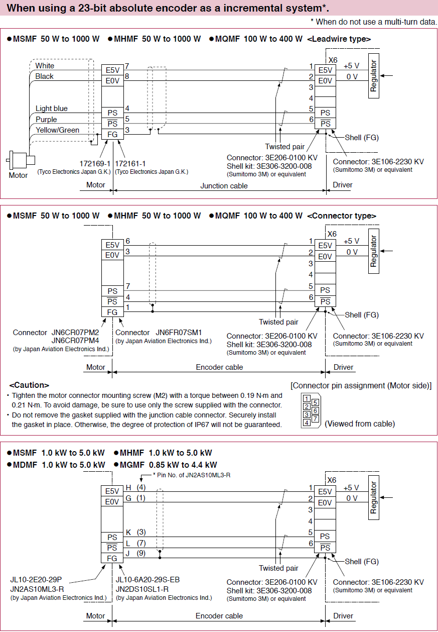
Wiring to the Connector, X6
|
|
Requests to customers (Automation Control Components & Industrial Device) [Excluding specific product]
Requests to customers (Automation Control Components & Industrial Device) [For specific product]
Requests to customers (FA Sensors & Components [Excluding motors])
Requests to customers (Dedicated to industrial motors)
- COMPONENTS & DEVICES
- FA SENSORS & COMPONENTS
- Fiber Sensors
- Photoelectric Sensors / Laser Sensors
- Micro Photoelectric Sensors
- Light Curtains / Safety Components
- Area Sensors
- Inductive Proximity Sensors
- Particular Use Sensors
- Sensor Options
- Wire-Saving Systems
- Programmable Controllers / Interface Terminal
- Human Machine Interface
- Pressure Sensors / Flow Sensors
- Measurement Sensors
- Static Control Devices
- Laser Markers / 2D Code Readers
- Machine Vision System
- Energy Management Solutions
- Timers / Counters / FA Components
- MOTORS
![]()