
 Business
> Industrial Devices
> Automation Controls Top
> FA Sensors & Components
> Programmable Controllers / Interface Terminal
> Programmable Controllers / Interface Terminal
> FP0H
> Part Number
> AFP0HC32ET
Business
> Industrial Devices
> Automation Controls Top
> FA Sensors & Components
> Programmable Controllers / Interface Terminal
> Programmable Controllers / Interface Terminal
> FP0H
> Part Number
> AFP0HC32ET
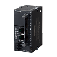
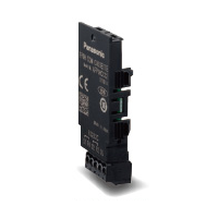
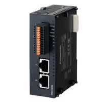
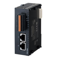
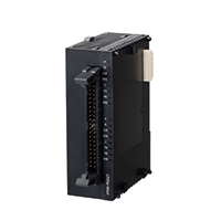
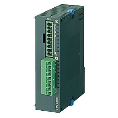
AFP0HC32ET | FP0H


|
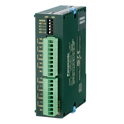
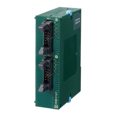
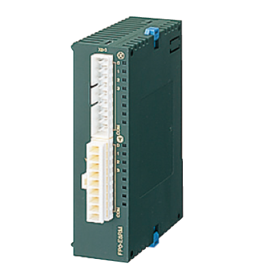
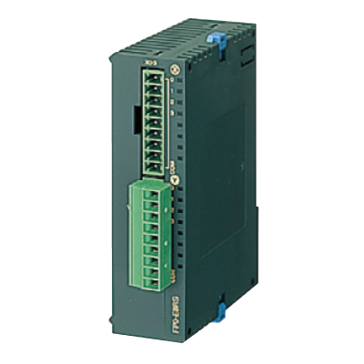
*Photo may vary from actual product.

 This product has been confirmed that it does not contain the 6 substances specified in EU RoHS Directive 2011/65/EU and the 4 substances specified in 2015/863/EU.
| Product Number | AFP0HC32ET |
| Part Number | AFP0HC32ET |
| Product | FP0H Control unit |
| Product name | FP0H |
As of April 19, 2024
Specifications and design of the products are subject to change without notice for the product improvement.
Spec Detail
| Item | Specifications |
|---|---|
| Product Number | AFP0HC32ET |
| Part Number | AFP0HC32ET |
Control specifications
| Item | Specifications | ||||
|---|---|---|---|---|---|
| Number of controllable I/O points | 32 points (Input: 16, Output: 16), When expanded: Max. 384 points | ||||
| Programming method / Control method | Relay symbol / Cyclic operation | ||||
| Program memory | Built-in flash ROM (no backup battery required) | ||||
| Number of instructions : Basic instructions | 120 types approx. | ||||
| Number of instructions : High-level instructions | 270 types approx. | ||||
| Program capacity | 24 k /32 k /40 k / 64 k steps Can be selected at system register No. 0 When the program capacity is changed, the number of words that can be used in the data register (DT) is also changed.
|
||||
| Operation speed | Basic instruction (NOT: /) : 10 ns/step approx. (Up to 10 k steps) ,0.18 μs/step approx. (10 k steps and later) Basic instruction (ST) : 40 ns/step approx. (Up to 10 k steps) ,0.65 μs/step approx. (10 k steps and later) High-level instruction (FOMV) : 0.14 μs/step approx. (Up to 10 k steps) , 1.2 μs/step approx. (10 k steps and later) |
||||
| Base scan time I/O refresh and base time |
Control unit: 100 μs or less approx. and FP0 / FP0R expanshion unit refresh time (Note) Note : Refresh times for FP0 / FP0R expansion units 8 points unit : Number of units×0.8ms 16 points unit : Number of units×1.0ms 32 points unit : Number of units×1.3ms 64 points unit : Number of units×1.9ms |
||||
| Operation memory : Relay : External input (X) | 1, 760 points (X0 to X109F)(Note 1, 2) Note 1 : The number of points that can be used depends on the combination of hardware. Note 2 : Some specifications are compatible with FPΣ. |
||||
| Operation memory : Relay : External output (Y) | 1, 760 points (X0 to X109F)(Note 1, 2) Note 1 : The number of points that can be used depends on the combination of hardware. Note 2 : Some specifications are compatible with FPΣ. |
||||
| Operation memory : Relay : Internal relay (R) | 8,192 points (R0 to R511F) (Note 1) Note 1 : Some specifications are compatible with FPΣ. |
||||
| Operation memory : Relay : Special internal relay (R) | 800 points (R9000 to R951F) | ||||
| Operation memory : Relay : Timer / Counter (T / C) | 1,024 points (initial setting, timer: 1,008 points, counter: 16 points)(Note) Note : An auxiliary timer instruction (F137) can be used to add the number of points. |
||||
| Operation memory : Relay : Link relay (L) | 2,048 points (L0 to L127F) | ||||
| Operation memory : Memory area : Data register (DT) | 12,285 words or 24,573 words or 32,765 words or 65,533 words(Note) Note : System register No. 0 (program capacity) can be configured to select the capacity of the data register (DT). |
||||
| Operation memory : Memory area : Special data register (DT) | 1,000 words (DT90000 to DT90999)(Note) Note : Some specifications are compatible with FPΣ. |
||||
| Operation memory : Memory area : Link data register (LD) | 256 words (LD0 to LD255) | ||||
| Operation memory : Memory area : Index register (I) | 14 words (I0 to ID) | ||||
| Differential points | Points for the program capacity | ||||
| Number of master control relay (MCR) | 256 points | ||||
| Number of labels (JP and LOOP) | 256 points | ||||
| Number of step ladders | 1,000 stages | ||||
| Number of subroutines | 500 subroutines | ||||
| Number of interrupt program | 9 programs •Input: 8 programs (INT0 to INT7) •Periodic: 1 program (INT24) |
||||
| Sampling trace | Available(Note) [Sampling by commands / Sampling at regular time intervals (For one sampling: 16 bits + 3 words), 1,000 samples] Note : Logging trace and sampling trace cannot be used at the same time. |
||||
| Comment storage | I/O comments, remarks and block comments can be stored. (no backup battery required, 1 M byte) |
||||
| PLC link function (Serial communication) |
Max. 16 units, link relays: 1,024 points, link registers: 128 words. (Data transfer and remote programming are not supported) |
||||
| Constant scan | Available (0 to 600 ms) | ||||
| Password | Available (32 digits) | ||||
| Program upload protection | Available | ||||
| Program protect function | Available | ||||
| Self-diagnosis function | Watchdog timer, program syntax check, etc. | ||||
| Program edition during RUN | Available | ||||
| SD memory card function | SD memory card project copy, Logging trace function (Note) SD memory card access instruction, Note : Logging trace and sampling trace cannot be used at the same time. |
||||
| Memory transfer | Available [Built-in memory (ROM ⇔ RAM)] | ||||
| High speed counter : Main unit input | Single-phase 4 channels (Max. 100 kHz each input) or 2-phase 2 channels (Max. 50 kHz each input)(Note) Note : The specifications are based on the rated input voltage of 24 V DC at +25 ℃ +77 ℉. The maximum operation frequency may be lower depending on the applied voltage, ambient temperature, and conditions of use. The maximum operation frequency varies depending on how the unit is used. |
||||
| Pulse output : Main unit output | 4 channels (Max. 100 kHz each axis)(Note) Note : The specifications are based on the rated input voltage of 24 V DC at +25 ℃ +77 ℉. The maximum operation frequency may be lower depending on the applied voltage, ambient temperature, and conditions of use. The maximum operation frequency varies depending on how the unit is used. |
||||
| PWM output : Main unit output | 4 channels (1 Hz to 70 kHz: 1,000 resolution / 70.001 kHz to 100 kHz: 100 resolution(Note) Note : The specifications are based on the rated input voltage of 24 V DC at +25 ℃ +77 ℉. The maximum operation frequency may be lower depending on the applied voltage, ambient temperature, and conditions of use. The maximum operation frequency varies depending on how the unit is used. |
||||
| Pulse catch input Interrupt input |
Total 8 points (with high speed counter) | ||||
| Periodical interrupt | 0.1 ms to 30 sec. | ||||
| Potentiometer (Volume) input | Not available | ||||
| Clock / calendar | Year (last two digits), month, day, hour (24-hour display), minute, second and day of week(Note 1, 2) Note 1 : Accuracy of the clock / calendar (within ± 90 seconds per month at +25 ℃ +77 ℉).If an error of the clock / calendar becomes a problem in the system, set an accurate time periodically. Note 2 : If the battery is not attached, calendar information is cleared when the power is turned off. It will be necessary to set the date when the power is turned on. |
||||
| Memory backup : Backup by instruction P13 | Data register: all area(Note) Note : Data can be rewritten up to 10,000 times. Hold / non-hold areas can be specified in the system registers. |
||||
| Memory backup : Auto-backup at power failure | Counter: 16 points Internal relay: 128 points Data register: 315 words Note : Data can be rewritten up to 10,000 times. Hold / non-hold areas can be specified in the system registers. |
||||
| Battery backup (only when a battery is installed) | Hold areas or non-hold areas can be specified by setting the system registers No.6 to No. 13. (It is also possible to make the setting for hold all points.) |
||||
| Battery life | 5 years or more under a production condition (operates for 8 hours per day) |
General specifications
| Item | Specifications |
|---|---|
| CE marking directive compliance | EMC Directive, RoHS Directive |
| Rated voltage | 24 V DC |
| Operating voltage range | 20.4 to 28.8 V DC |
| Current consumption | 170 mA or less |
| Allowed momentary power off time | 4 ms (at 20.4 V DC), 10 ms (24 V DC or higher) |
| Operating temperature | 0 to +55 ℃ +32 to +131 ℉, At storage: -40 to +70 ℃ - 40 to +158 ℉ |
| Operating humidity | 10 to 95 % RH (at +25 ℃ +77 ℉, no dew condensation allowed), At storage: 10 to 95 % RH (at +25 ℃ +77 ℉, no dew condensation allowed) |
| Withstand voltage | (Detection current: 5 mA) 500 V AC for 1 minute Input and output terminals ⇔ power and functional ground terminals Input terminals ⇔ Output terminals |
| Insulation resistance | (Test voltage: 500 V DC) 100 MΩ or more Input and output terminals ⇔ power and functional ground terminals Input terminals ⇔ Output terminals |
| Vibration resistance | 5 to 8.4 Hz, single amplitude of 3.5 mm 0.138 in, 8.4 to 150 Hz, constant acceleration of 9.8 m/s2, for 10 times each in X, Y, and Z directions (1 octave/min.) (JIS B 3502, IEC 61131-2) |
| Shock resistance | 147 m/s2, 4 times each in X, Y, and Z directions (JIS B 3502, IEC 61131-2) |
| Noise resistance | 1,000 V (p-p) with pulse widths 50 ns and 1 μs (using a noise simulator) (Power supply terminal) |
| Operating condition | Free from corrosive gasses and excessive dust |
| Overvoltage class | Category II |
| Level of contamination | Pollution level 2 |
| Net weight | 130 g approx. |
COM0 port communication specifications
| Item | Specifications |
|---|---|
| Interface | RS-232C, three-wire system, 1 channel (Not insulated) |
| Transmission distance | 15 m 49.213 ft |
| Communication configuration | 1 : 1 communication |
| Communication method | Half-duplex system |
| Synchronous method | Start-stop synchronization system |
| Transmission cable | Multi-conductor shielded wire |
| Communication speed (Specified at the system registers) |
1,200(Note), 2,400(Note), 4,800, 9,600, 19,200, 38,400, 57,600, 115,200, 230,400 bits/sec. Note : System register no. 415 cannot be used to set the baud rate to 1,200 bps. To set the baud rate to 1,200 bps, use the SYS1 instruction. If the baud rate of any of the COM ports is 2,400 bps or lower, F-ROM access will slow down. Example) F12(ICRD) instruction, P13(ICWT) instruction, etc. |
| Transmission format : Data length | 7 bits / 8 bits |
| Transmission format : Parity | none / odd / even |
| Transmission format : Stop bit | 1 bit / 2 bits |
| Transmission format : Start code | with STX / without STX |
| Transmission format : End code | CR / CR + LF / none / ETX / Time (0 to 100.00 ms) |
| Data transmission order | Transmit from bit 0 in character units |
| Communication mode | MEWTOCOL-COM (Master / Slave) (Computer link) General-purpose communication PLC link MODBUS RTU (Master / Slave) |
| Remark | The start and end codes can be used only for general-purpose serial communications. The unit No. (station number) can be selected at system register No. 410. |
LAN communication port specifications
| Item | Specifications |
|---|---|
| Communication interface | Ethernet 100BASE-TX / 10BASE-T |
| Communication speed | 100 Mbps, 10 Mbps auto negotiation function |
| Total cable length | 100 m 328.084 ft (500 m 1640.420 ft when a repeater is used) |
| Number of simultaneous connections | Max. 10 (system connection: 1, user connection: 9) |
| Communication method | Full duplex / Half-duplex system |
| Communication protocol (Communication layer) |
TCP / IP, UDP |
| DNS | Supports name servers |
| DHCP | Automatic IP address acquisition |
| FTP server / Client | File transmission, server function, No. of users:1 Client function, Data file transfer |
| SNTP | Time adjustment function |
| General-purpose communication | 4 kB / 1 connection (user connection: 1 to 9) (Note) Note : General-purpose communications can be up to 4 kB (reception) and up to 2 kB (transmission) per connection. |
| Dedicated communication | EtherNet/IP MEWTOCOL-COM (Master / Slave) (Computer link) MODBUS-TCP (Master / Slave) MEWTOCOL-DAT (Master / Slave) General-purpose communication MC protocol (Note 1) (Master / Slave) Note : MC protocol is a short form denoting MELSEC communication protocol; MELSEC is a registered trademark of Mitsubishi Electric Corporation.QnA compatible 3E frame, only binary (bulk writing and bulk reading) use is available. |
USB port specifications
| Item | Specifications |
|---|---|
| Standard | USB2.0 Full speed (USB mini B type) |
| Communication function | Computer link (slave) |
Dedicated power supply output port specifications for GT series programmable display
| Item | Specifications |
|---|---|
| Terminal:5V | Connecting programmable display model : For 5 V DC type GT02 series Programmable Display |
Input specifications
| Item | Specifications |
|---|---|
| Rated input voltage | 24 V DC |
| Applied voltage range | 21.6 to 26.4 V DC |
| Rated input current | High-speed part (X0 to X7) : 8 mA approx. Low-speed part (X8 to XF) : 3.5 mA approx. |
| Input points per common | 16 points/common (Either the positive or negative of the input power supply can be connected to the common terminal.) |
| Min. ON voltage / Min. ON current | High-speed part (X0 to X7) : 19.2 V DC / 6 mA Low-speed part (X8 to XF) : 19.2 V DC / 3 mA |
| Max. OFF voltage / Max. OFF current | 2.4 V DC / 1 mA |
| Input impedance | High-speed part (X0 to X7) : 3 kΩ approx. Low-speed part (X8 to XF) : 6.8 kΩ approx. |
| Response time : OFF→ON | <High-speed part (X0 to X7)> 135 μs or less: normal input 5 μs or less: high speed counter, pulse catch, interrupt input settings <Low-speed part (X8 to XF)> 1 ms or less: normal input only Note: The input time constant (0.1 to 256 ms) can be specified. |
| Response time : ON→OFF | Same as above |
| Action indicator | LED display |
Output specifications
| Item | Specifications |
|---|---|
| Output type | Nch open drain |
| Rated load voltage | 5 to 24 V DC |
| Load voltage allowable range | 4.75 to 26.4 V DC |
| Rated load current | 0.3 A (For Y0, Y1, Y3, Y4, Y8,Y9, YB,YC), 0.1 A (For Y2, Y5, Y6, Y7, YA, YD, YE, YF) |
| Max. surge current | High-speed part (For Y0, Y1, Y3, Y4, Y8, Y9, YB, YC) : 1.0 A, Low-speed part (For Y2, Y5, Y6, Y7, YA, YD, YE, YF) : 0.5 A |
| OFF state leakage current | 110 μA or less |
| ON state voltage drop | 0.5 V DC or less |
| Overcurrent protection | Provided (automatically protected for each 8 points) |
| Output points per common | 16 points/common (Y0 to YF / 1 common) |
| Response time : OFF→ON | High-speed part (For Y0, Y1, Y3, Y4, Y8, Y9, YB, YC) : 2 μs or less, Low-speed part (For Y2, Y5, Y6, Y7, YA, YD, YE, YF) : 1 ms or less |
| Response time : ON→OFF | High-speed part (For Y0, Y1, Y3, Y4, Y8, Y9, YB, YC) : 5 μs or less, Low-speed part (For Y2, Y5, Y6, Y7, YA, YD, YE, YF) : 1 ms or less |
| Surge absorber | Zener diode |
| Operating mode indicator | LED display |
Current consumption
| Item | Specifications |
|---|---|
| Current consumption | Refer to "FP0H Specifications - Current consumption" for the current consumption. |
Accessories (Option)


BY EMAIL


Requests to customers (Automation Control Components & Industrial Device) [Excluding specific product]
Requests to customers (Automation Control Components & Industrial Device) [For specific product]
Requests to customers (FA Sensors & Components [Excluding motors])
Requests to customers (Dedicated to industrial motors)
- COMPONENTS & DEVICES
- FA SENSORS & COMPONENTS
- Fiber Sensors
- Photoelectric Sensors / Laser Sensors
- Micro Photoelectric Sensors
- Light Curtains / Safety Components
- Area Sensors
- Inductive Proximity Sensors
- Particular Use Sensors
- Sensor Options
- Wire-Saving Systems
- Programmable Controllers / Interface Terminal
- Human Machine Interface
- Pressure Sensors / Flow Sensors
- Measurement Sensors
- Static Control Devices
- Laser Markers / 2D Code Readers
- Machine Vision System
- Energy Management Solutions
- Timers / Counters / FA Components
- MOTORS
![]()