
 Business
> Industrial Devices
> Automation Controls Top
> AFP7MXY32DWDH
Business
> Industrial Devices
> Automation Controls Top
> AFP7MXY32DWDH
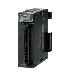
AFP7MXY32DWDH | Multi input/output unit


|
*Photo may vary from actual product.
- Discontinued
 September 30, 2022
| Product Number | AFP7MXY32DWDH |
| Part Number | AFP7MXY32DWDH |
| Product | FP7 Multi Input/Output Unit |
| Details | Positioning type |
| Product name | Multi input/output unit |
 FP7
FP7
 -
-
 -
-
-
 Suggested alternative products may be different under the conditions of use.
Contact us
Suggested alternative products may be different under the conditions of use.
Contact us
For recommended substitutes, please use the combination of FP7 multi input / output unit (AFP7MXY32DWD) and FP7 positioning unit (AFP7PP0□□).
*The program is not compatible.
Spec Detail As of September 30, 2022
| Item | Specifications |
|---|---|
| Product Number | AFP7MXY32DWDH |
| Part Number | AFP7MXY32DWDH |
Function specifications
| Item | Specifications |
|---|---|
| Basic input and output : Number of occupied I/O points | Input/Output : 96 points each (6 words) |
| Basic input and output : Number of external I/O points | Input: 16 points, Output: 16 points |
| Basic input and output : Input time constant setting | None, 0.5 μs, 1 μs, 2 μs, 4 μs, 8 μs, 16 μs, 32 μs, 64 μs, 96 μs, 128 μs, 256 μs, 2 ms, 4 ms, 8 ms Setting possible in 2-point units |
| Basic input and output : Output polarity setting | No output, N channel, P channel, Both channels (push pull output), Differential output Setting possible in 4-point units |
| Interrupt : Number of points | 8 points/unit (Max. of 8 units can be used with FP7 system.) |
| Interrupt : Mode | Non-interrupt unit, Interrupt unit (Set using DIP switches) |
| Interrupt : Interrupt condition setting | Terminal input, Comparison match |
| Counter : Counter type | Ring counter Linear counter |
| Counter : Input mode | Direction distinction, Individual input, Phase input |
| Counter : Number of channels | 4 channels (Note): When using elapsed value hold function, number of channels will be limited. |
| Counter : Counting range | Signed 32 bit (-2,147,483,648 to +2,174,483,647) Setting possible of upper and lower limits |
| Counter : Max. counting speed | 5 V input voltage: 500 kHz 12 V input voltage: 500 kHz (350 kHz with phase input) 24 V input voltage: 250 kHz (180 kHz with phase input) (Note): With 50 % duty input pulse. |
| Counter : Min. input pulse width | 0.5 μs |
| Counter : Comparison output setting | Max. 8 points Terminal input counter: 4 channels |
| Counter : Others | Transfer multiplication function (× 1, × 2, × 4) Elapsed value offset / preset function Elapsed value hold function, setting of upper / lower count limits Input pulse frequency measurement Overflow / underflow detection |
| Pulse output : Number of channels | 4 channels |
| Pulse output : Output mode | Direction distinction, Individual output, Phase output, Comparison match stop |
| Pulse output : Output terminals : Pulse output function | 2 terminals / channel (B11 to B18 terminals) |
| Pulse output : Output terminals : PWM output function | 1 terminal / channel (B11, B13, B15 and B17 terminals) |
| Pulse output : Output frequency : Pulse output function | 1 to 500 kHz (Note) (Settable by 1 Hz) (Note): When push pull setting or output current is 0.1 A. Varies according to load. |
| Pulse output : Output frequency : PWM output function | 1 to 100 kHz (Note) (Settable by 1 Hz) (Note): When push pull setting or output current is 0.1 A. Varies according to load. |
| Pulse output : Duty ratio : Pulse output function | 50 % approx. (Fixed) |
| Pulse output : Duty ratio : PWM output function | 0 to 100 % (Settable by 0.1%) |
| Pulse output : Other functions | Pulse number measurement function (dedicated pulse counter 4 channels) |
Positioning function specifications
| Item | Specifications |
|---|---|
| Number of axes controlled | Max. 4 axes |
| Common specifications : Position setting mode | Increment, Absolute |
| Common specifications : Output interface | Transistor open collector output, Push-pull, Line driver (Note): The number of axes is reduced when setting Line driver. |
| Common specifications : Pulse output method | Pulse + Sign, CW + CCW |
| Common specifications : Max. output frequency | 500 kHz |
| Common specifications : Output pulse duty ratio | When using table setting mode : 50 % (Fixed) |
| Common specifications : Control unit | Pulse |
| Position control : Position setting range | -1,073,741,824 to +1,073,741,823 pulses |
| Position control : Speed command range | Pulse : 1 to 500,000 Hz |
| Position control : Max. operation speed | 500 kHz |
| Position control : Acceleration/deceleration method | Linear acceleration/deceleration |
| Position control : Acceleration time | 1 to 10,000 ms (Settable by 1 ms) |
| Position control : Deceleration time | 1 to 10,000 ms (Settable by 1 ms) |
| Position control : Number of positioning tables | 20 tables for each axis (Up to 2 tables can be executed consecutively.) |
| Position control : Control method (Single axis) | PTP control (E point control, C point control), CP control (P point control), Speed control (J point control) (Note 1): The J point control is executable only for the two axes of CH0 and CH1. (Note 2): When performing the J point control or JOG operation, the speed can be changed after the startup. |
| Position control : Control method (2-axis linear interpolation) | E point, P point, C point controls, Composite speed or Long axis speed setting |
| Position control : Dwell time | 0 to 32,767 ms (Settable by 1 ms) |
| JOG operation : Speed command range | Pulse : 1 to 500,000Hz (Note): When performing the J point control or JOG operation, the speed can be changed after the startup. |
| JOG operation : Acceleration/deceleration method | Linear acceleration/deceleration |
| JOG operation : Acceleration time | 1 to 10,000 ms (Settable by 1 ms) |
| JOG operation : Deceleration time | 1 to 10,000 ms (Settable by 1 ms) |
| Home return : Speed command range | Pulse : 1 to 500,000 Hz |
| Home return : Acceleration/deceleration method | Linear acceleration/deceleration |
| Home return : Acceleration time | 1 to 10,000 ms (Settable by 1 ms) |
| Home return : Deceleration time | 1 to 10,000 ms (Settable by 1 ms) |
| Home return : Return method | DOG methods (3 types), Home position method, Data set method |
| Stop function : Deceleration stop | Performs deceleration stop in the deceleration time of a running operation for each axis. |
| Stop function : Emergency stop | Stops in a deceleration time specified for the emergency stop for each axis. |
| Stop function : Limit stop | Stops in a deceleration time specified for the limit input for each axis. |
| Stop function : System stop | Stops all axes immediately. |
COMMON GENERAL SPECIFICATIONS
| Item | Specifications |
|---|---|
| Ambient temperature | 0 to +55 ℃ +32 to +131 ℉, Storage: -40 to +70 ℃ -40 to +158 ℉ |
| Ambient humidity | 10 to 95 % RH (at +25 ℃ +77 ℉, no condensation), Storage: 10 to 95 % RH (at +25 ℃ +77 ℉, no condensation) |
| Vibration resistance | 5 to 8.4 Hz, single amplitude of 3.5 mm 0.138 in, 1 sweep/min. (IEC 61131-2) ; 8.4 to 150 Hz, constant acceleration of 9.8 m/s2, 1 sweep/min. (IEC 61131-2), 10 times each in X, Y, and Z directions |
| Shock resistance | 147 m/s2 or more , 3 times each in X, Y, and Z directions (IEC61131-2) |
| Noise immunity | 1,000 V [p-p] with pulse width 50 ns and 1 μs (using a noise simulator) |
| Operating condition | Free from corrosive gasses and excessive dust |
INDIVIDUAL GENERAL SPECIFICATIONS
| Item | Specifications |
|---|---|
| Rated voltage range | - |
| Current consumption | 100 mA or less |
| Net weight | 100 g approx. |
Applicable Products As of September 30, 2022
CONTACT US
If you have any questions, please select the option below to contact us or find answers.
CONTACT US
BY EMAIL
BY EMAIL
Please click your area to select country or region


Requests to customers (Automation Control Components & Industrial Device) [Excluding specific product]
Requests to customers (Automation Control Components & Industrial Device) [For specific product]
Requests to customers (FA Sensors & Components [Excluding motors])
Requests to customers (Dedicated to industrial motors)
- COMPONENTS & DEVICES
- FA SENSORS & COMPONENTS
- Fiber Sensors
- Photoelectric Sensors / Laser Sensors
- Micro Photoelectric Sensors
- Light Curtains / Safety Components
- Area Sensors
- Inductive Proximity Sensors
- Particular Use Sensors
- Sensor Options
- Wire-Saving Systems
- Programmable Controllers / Interface Terminal
- Human Machine Interface
- Pressure Sensors / Flow Sensors
- Measurement Sensors
- Static Control Devices
- Laser Markers / 2D Code Readers
- Machine Vision System
- Energy Management Solutions
- Timers / Counters / FA Components
- MOTORS
![]()