
 Business
> Industrial Devices
> Automation Controls Top
> FA Sensors & Components
> Programmable Controllers / Interface Terminal
> Programmable Controllers / Interface Terminal
> FP-X0
> Part Number
> AFPX0L14R
Business
> Industrial Devices
> Automation Controls Top
> FA Sensors & Components
> Programmable Controllers / Interface Terminal
> Programmable Controllers / Interface Terminal
> FP-X0
> Part Number
> AFPX0L14R
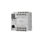
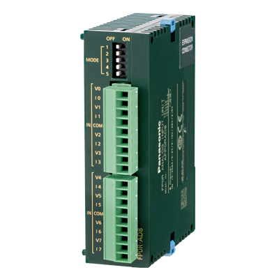
AFPX0L14R | FP-X0


|
*Photo may vary from actual product.

 This product has been confirmed that it does not contain the 6 substances specified in EU RoHS Directive 2011/65/EU and the 4 substances specified in 2015/863/EU.
| Product Number | AFPX0L14R |
| Part Number | AFPX0L14R |
| Product | FP-X0 Control units |
| Product name | FP-X0 |
As of April 20, 2024
Specifications and design of the products are subject to change without notice for the product improvement.
Spec Detail
| Item | Specifications |
|---|---|
| Product Number | AFPX0L14R |
| Part Number | AFPX0L14R |
Performance specifications
| Item | Specifications |
|---|---|
| Controllable I/O points : Control unit | DC input: 8 points Relay output: 4 points Transistor output: 2 points |
| Controllable I/O points : When using FP-X E16 expansion I/O units | - |
| Controllable I/O points : When using FP-X E30 expansion I/O units | - |
| Controllable I/O points : When using FP0R expansion units | - |
| Programming method/Control method | Relay symbol/Cyclic operation |
| Program memory | Built-in Flash-ROM (Free of backup battery) |
| Program capacity | 2.5 k steps |
| No. of instruction : Basic commands | Approx. 114 kinds |
| No. of instruction : High-level commands | Approx. 230 kinds |
| Processing speed | 0.08 μs/step for basic commands, 0.32 μs for high-level commands (MV commands) |
| Processing speed : Basic time | 0.15 ms or less |
| I/O refreshing + basic time | When using E16: 0.4 ms × No. of units When using E30: 0.5 ms × No. of units When using FP0 expansion adapters: 1.4 ms + the refreshing time of the FP0 expansion unit |
| Memory for processing : Relays : External input (X) | 960 points (Note) The actual usable points depend on the combination of the hardware. |
| Memory for processing : Relays : External output (Y) | 960 points (Note) The actual usable points depend on the combination of the hardware. |
| Memory for processing : Relays : Internal relay (R) | 1,008 points |
| Memory for processing : Relays : Special internal relay (R) | 224 points |
| Memory for processing : Relays : Timer・Counter (T/C) | ・256 points(Note) ・Timer: (1 ms, 10 ms, 100 ms, 1 s) × 32,767 ・Counter: 1 to 32,767 (Note) The points of the timer can be added as required. |
| Memory for processing : Relays : Link relay (L) | No |
| Memory for processing : Memory area : Data register (DT) | 2,500 words |
| Memory for processing : Memory area : Special data register (DT) | 420 words |
| Memory for processing : Memory area : Link data register (LD) | No |
| Memory for processing : Memory area : File registration (FL) | No |
| Memory for processing : Memory area : Index register (I) | 14 words (IO to ID) |
| Differential points | Equivalent to program capacity |
| Master control relay (MCR) | 32 points |
| Label number (JP+LOOP) | 100 points |
| No. of step programs | 128 (Engineering) |
| No. of subroutines | 100 |
| No. of interrupt programs | Input: 8 programs timing: 1 program |
| Sampling trace | No |
| Comments storage | All of the I/O comments,explanations and block comments can be saved. (Free of backup battery, 328 k bytes) |
| PLC link function | No |
| Constant scan | In unit of 0.5 ms: 0.5 ms to 600 ms |
| Password | Available (4 or 8 digits) |
| Upload protection | Available |
| Self-diagnosis function | Checks of the watchdog timer and the program syntax |
| Program editting during Run | Available (Capacity modified simultaneously: 128 steps) But comments cannot be modified during the process. |
| Downloading during Run | Available |
| High-speed counter : Body input | 1-phase, 4-channel (20 kHz max.) and 2-phase, 2-channel (20 kHz max.) (Note) The rated voltage is 24 V DC at +25 ℃+77℉. The frequency may fall according to the changes of the voltage, temperature and operating conditions. (Note) The maximum frequency may vary with the difference of the operating method. |
| Pulse output/PWM output : Body output | Pulse: 1-channel (20 kHz max.) or PWM: 1-channel (1.6 kHz max.) (Note) The rated voltage is 24 V DC at 25 ℃. The frequency may fall according to the changes of the voltage, temperature and operating conditions. (Note) The maximum frequency may vary with the difference of the operating method. |
| Pulse catch input/Interrupt program | 8 points (High-speed counting and interrupt input included) |
| Periodical interrupt | 0.5 ms unit: 0.5 ms to 1.5 sec., 10 ms unit: 10 ms to 30 sec. |
| Analog input | No |
| Calendar/clock | No |
| Flash ROM backup : Backup made according to commands of F12 and P13 | Data memory (2,500 words) (Note) The allowable writing operation is within 10,000 times. Areas to be held and not held can be specified using the system registers. |
| Flash ROM backup : Automatic backup when power OFF | Counter: 6 points (C250 to C255) Process value of the counter: 6 points (EV250 to EV255) Internal relays: 5 points (WR58 to WR62) Data memory: 300 words (DT2200 to DT2499) (Note) The allowable writing operation is within 10,000 times. Areas to be held and not held can be specified using the system registers. |
| Backup battery | No |
| RS485 communication port | No |
General specifications
| Item | Specifications |
|---|---|
| CE marking directive compliance | Low Voltage Directive,EMC Directive,RoHS Directive |
| Operating temperature | 0 to +55℃ +32 to +131℉ |
| Storage temperature | -40 to +70℃−40 to +158℉ |
| Operating humidity | 10 to 95% RH (at 25 ℃, no condensation) |
| Storage humidity | 10 to 95% RH (at 25 ℃, no condensation) |
| Withstand voltage | 2,300 V AC, 1 minute ・Input terminals ⇔ Relay output terminals ・All of the transistor output terminals ⇔ All of the relay output terminals ・All of the input terminals⇔ All of the power supply terminals and functional ground terminals ・All of the relay output terminals ⇔ All of the power supply terminals and functional ground terminals ・All of the transistor output terminals ⇔ All of the power supply terminals and functional ground terminals 1,500 V AC, 1 minute ・Power supply terminals ⇔ Ground terminals 500 V AC, 1 minute ・Input terminals ⇔ Transistor output terminals (Note) The programmable port, RS485 communication port and the internal digital circuit part are non-insulation type. (Note) The cut-off current is 5 mA (The default value when shipped from the factory) . |
| Insulation resistance | 100 MΩ min. (500 V DC insulation resistance meter) ・Input terminals ⇔ Output terminals ・All of the transistor output terminals ⇔ All of the relay output terminals ・All of the input terminals ⇔ All of the power supply terminals and functional ground terminals ・All of the output terminals ⇔ All of the power supply terminals and functional ground terminals ・Power supply terminals ⇔ Ground terminals (Note) The programmable port, RS485 communication port and the internal digital circuit part are non-insulation type. |
| Vibration resistance | 5 to 8.4 Hz, 3.5 mm amplititude in one direction, 1 scan/1 minute 8.4 to 150 Hz,fixed acceleration of 9.8 m/s2, 1 scan/1 minute 10 minutes in X,Y,Z direction each |
| Shock resistance | 147 m/s2, 4 times in X, Y, Z directions each |
| Noise resistance | 1,500 V [p-p] pulse width 50 ns, 1 μs (Measured from nosie simulation method AC power supply termianls) |
| Operating condition | No corrosive gases or too much dust |
| Overvoltage class | II |
| Level of contamination | 2 |
| Weight | Net weight:approx. 280g |
Power supply specifications(AC power supply)
| Item | Specifications |
|---|---|
| Rated voltage | 100 to 240 V AC |
| Applied voltage range | 85 to 264 V AC |
| Inrush current | 35A max. (at 240 V AC and 25℃+77℉) |
| Momentary power off time | 10 ms (when 100 V AC used) |
| Frequency | 50/60 Hz (47 to 63 Hz) |
| Leakage current | 0.75 mA max.between the input and protectice ground terminals |
| Service life of built-in power supply | 20000 h (at 55℃+131℉) |
| Fuse | Built-in (replacement disabled) |
| Insulation system | Transformer isolation |
| Screw of terminal block | M3 |
Input specifications
| Item | Specifications |
|---|---|
| Insulation method | Optical coupler |
| Rated input voltage | 24 V DC |
| Applied voltage range | 21.6 V DC to 26.4 V DC |
| Rated input current | Approx. 3.5 mA (Control uint: X0 to X3) Approx. 4.3 mA (Control unit: X4 and the following ones) |
| Input points per common | 8 points/COM (Input power supply +/- are both available.) |
| Min. ON voltage/Min. ON current | 19.2 V DC/3 mA |
| Max. OFF voltage/Max. OFF current | 2.4 V DC/1.0 mA |
| Input impedance | Approx. 6.8 kΩ (Control units: X0 to X3) Approx. 5.6 kΩ (control unit X4 and the following ones) |
| Response time : OFF→ON | For X0 to X3 ・common input: 1 ms max. ・When setting high-speed counter, pulse catching input and interrupt input: 25 μs max.(Note) X4 and the following ones ・1 ms max. (Note) The specifications mentioned above are at rated 24 V DC and operationg temperature of 25℃. |
| Response time : ON→OFF | Same as the above. |
| Action indicator | LED indication |
| EN61131-2 application type | TYPE 3 standard (Depending on the above-mentioned specifi cations) |
Output specifications(Relay output specifictions)
| Item | Specifications |
|---|---|
| Insulation method | Relay insulation |
| Output form | 1a output (Relay replacement disabled) |
| Rated control capacity (Resistance load) | 2A 250 V AC, 2A 30 V DC (per point) (Note) There are restrictions on the rated current for each output block. Y2 to Y5 (4 points) Max. 6A in total. |
| Output points per common | 1 point/COM×2, 2 points/COM×1 |
| Response time : OFF→ON | Approx. 10 ms |
| Response time : ON→OFF | Approx. 8 ms |
| Life : Mechanical | 20,000,000 times min. (Switching frequency 180 times/minute) |
| Life : Electrical | 100,000 times min. (Depending on the rated control capacity, switching frequency of 20 times/minute) |
| Surge absorber | No |
| Action indicator | LED indication |
Output specifications(Transistor (NPN) output specifications)
| Item | Specifications |
|---|---|
| Insulation method | Optical coupler |
| Output method | Open-collector |
| Rated load voltage | 5 to 24 V DC |
| Allowable range of load voltage | 4.75 to 26.4 V DC |
| Max. load current | 0.5 A |
| Max. impact current | 1.5 A |
| Output points per common | 2 points/COM |
| Leakage current at OFF status | 1 μA max. |
| Max. voltage drop at ON status | 0.3 V DC max. |
| Response time (at 25℃) : OFF→ON | 10 μs max. (Load current over 15 mA) |
| Response time (at 25℃) : ON→OFF | 40 μs max. (Load current over 15 mA) |
| External power supply (Positive and negative teiminals) | Voltage: 21.6 to 26.4 V DC Current: 15 mA max. |
| Surge absorber | Zener diode |
| Action indicator | LED indication |
Accessories (Option)

BY EMAIL


Requests to customers (Automation Control Components & Industrial Device) [Excluding specific product]
Requests to customers (Automation Control Components & Industrial Device) [For specific product]
Requests to customers (FA Sensors & Components [Excluding motors])
Requests to customers (Dedicated to industrial motors)
- COMPONENTS & DEVICES
- FA SENSORS & COMPONENTS
- Fiber Sensors
- Photoelectric Sensors / Laser Sensors
- Micro Photoelectric Sensors
- Light Curtains / Safety Components
- Area Sensors
- Inductive Proximity Sensors
- Particular Use Sensors
- Sensor Options
- Wire-Saving Systems
- Programmable Controllers / Interface Terminal
- Human Machine Interface
- Pressure Sensors / Flow Sensors
- Measurement Sensors
- Static Control Devices
- Laser Markers / 2D Code Readers
- Machine Vision System
- Energy Management Solutions
- Timers / Counters / FA Components
- MOTORS
![]()