
 Business
> Industrial Devices
> Automation Controls Top
> Service & Support
> FA Technical Support
> Technical Guide (FA Sensors)
> Displacement Sensors
> Eddy Current Type Displacement Sensor
Business
> Industrial Devices
> Automation Controls Top
> Service & Support
> FA Technical Support
> Technical Guide (FA Sensors)
> Displacement Sensors
> Eddy Current Type Displacement Sensor
Eddy Current Type Displacement Sensor - Displacement Sensors
|
Eddy Current Type Displacement Sensor
Principle of detection
|
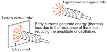
The eddy current type displacement sensors produce a high-frequency magnetic field by applying a high-frequency current to the coil inside the sensor head. If there is a measurement object (metal) within this magnetic field, then excess current is produced around the magnetic flux that passes through the object surface due to the electromagnetic induction effect. This changes the impedance of the coil within the sensor head. |
 |
Output correction according to materials
The sensors are adjusted so that a standard sensing object is 0 V when in a direct contact and 5 V when at the maximum sensing range (full scale). Then, the output is corrected so that the sensing range becomes proportional to the analog output according to the materials being sensed.
GP-X series
|
The output is linearly corrected for three materials [stainless steel (SUS304), iron, and aluminum]. |
Optimal correction of the output feature 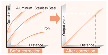 |
GP-A series
|
The output is linearly corrected with iron as the standard sensing object. Therefore, other materials (stainless steel, aluminum, copper, etc.) will have different output characteristics. Refer to the sensing characteristics in the catalog. In addition, fine adjustment is possible through the shift adjustment and span adjustment. |
Typical 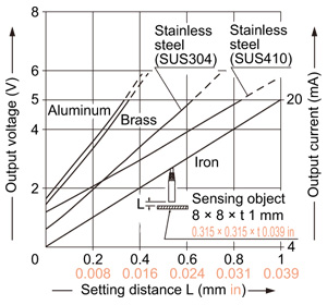 |
Operation principles of the GP-X series and GP-A series
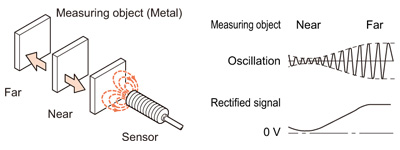
As the distance between the measurement object (metal) and the sensor head becomes smaller, then greater excess current is produced and the loss of energy at the sensor head increases. As a result, when the distance is made closer, the oscillation becomes smaller. When the distance is greater, the oscillation becomes greater. The sensors rectify the variations in the oscillation and that causes a change of the DC voltage.
The rectified signal is almost proportional to the distance. However, linearity is corrected through linearization and an output that is proportional to the distance can be obtained.
|
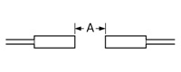
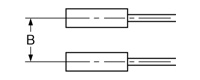
Mutual interference
When placing the same model sensors close to each other, the resolution may become poor due to the influence of the same frequency magnetic field of the other sensors.
This is called mutual interference. There are methods to prevent mutual interference as shown below.
<Mount the sensors with enough space so that no interference is caused.>
|
|
(For details, refer to the section "PRECAUTIONS FOR PROPER USE" of each sensor.)
<Use interference prevention function. (GP-X)>
<Use along with a different frequency type. (GP-A)>
Related Products
Download
- displacement_e.pdf

|
BY EMAIL


Requests to customers (Automation Control Components & Industrial Device) [Excluding specific product]
Requests to customers (Automation Control Components & Industrial Device) [For specific product]
Requests to customers (FA Sensors & Components [Excluding motors])
Requests to customers (Dedicated to industrial motors)
- COMPONENTS & DEVICES
- FA SENSORS & COMPONENTS
- Fiber Sensors
- Photoelectric Sensors / Laser Sensors
- Micro Photoelectric Sensors
- Light Curtains / Safety Components
- Area Sensors
- Inductive Proximity Sensors
- Particular Use Sensors
- Sensor Options
- Wire-Saving Systems
- Programmable Controllers / Interface Terminal
- Human Machine Interface
- Pressure Sensors / Flow Sensors
- Measurement Sensors
- Static Control Devices
- Laser Markers / 2D Code Readers
- Machine Vision System
- Energy Management Solutions
- Timers / Counters / FA Components
- MOTORS
![]()