
 Business
> Industrial Devices
> Automation Controls Top
> Service & Support
> FA Technical Support
> Technical Guide (FA Sensors)
> Photoelectric Sensors
> Classification methods & Classification
Business
> Industrial Devices
> Automation Controls Top
> Service & Support
> FA Technical Support
> Technical Guide (FA Sensors)
> Photoelectric Sensors
> Classification methods & Classification
Classification methods & Classification - Photoelectric Sensors
|
Classification methods & Classification
Classification methods
There are various types of photoelectric sensors. Four different methods of classification, depending on the objective considered, are explained here.
(1) Classification by structure
|
This classification is based on the manner in which the circuit configuration elements are built-in or separated. This classification is useful to select sensors in view of the mounting space, power supply and noise immunity. |
|
(2) Classification by sensing mode
|
This classification is based on how the light is emitted and received and on the sensor shape. This classification is useful to select sensors in view of the sensing object size and the surrounding conditions. |
|
(3) Classification by beam source
|
This classification is based on the type of beam source used. |
|
(4) Classification by output circuit
|
This classification is based on the type of output circuit and the output voltage. |
|
Classification
(1) Classification by structure
| Type | Outline and Features | |
|---|---|---|
| Amplifier built-in | 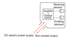 |
Since the amplifier is built-in, just connecting the DC electric power supply can provide a Non-contact output. |
| Power supply built-in | 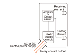 |
Since all necessary functions of a photoelectric sensor are incorporated, just connecting the electric power supply (100 V / 200 V AC) can provide a relay contact output. |
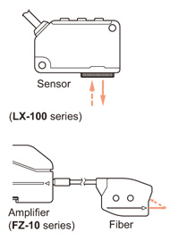
| Amplifier-separated | 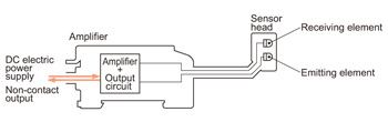 |
As the sensor head contains only the emitting and the receiving elements, its size can be made small. Further, the sensitivity adjustment can be done from a remote place. |
| Fiber | 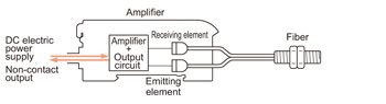 |
It has supreme environmental resistance, since the sensing portion (fiber) contains absolutely no electrical parts. |
Feature comparison table
| Feature | Sensor head size |
Noise immunity |
Lifetime | Ease of use |
|---|---|---|---|---|
| Amplifier built-in | ○ | ○ | ◎ | ○ |
| Power supply built-in | △ | ○ | △ | ◎ |
| Amplifier-separated | ◎ | △ | ◎ | ○ |
| Fiber | ◎ | ◎ | ◎ | ◎ |
| ◎ | : | Excellent |
|---|---|---|
| ○ | : | Good |
| △ | : | Fair |
(2) Classification by sensing mode
Thru-beam
| Type | Outline and Features | |
|---|---|---|
| General purpose | Detects an object that interrupts the light beam traveling from the emitter to the receiver.
|
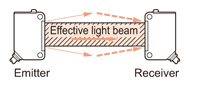 |
| U-shaped | The emitter and the receiver are in one enclosure.
|
 |
| Area | Light curtain or area sensor is made up of arrayed emitting and receiving elements.
|
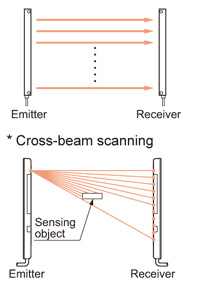 |
Retroreflective
| Type | Outline and Features | |
|---|---|---|
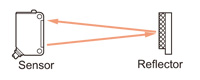
| General purpose | Detects an object that has a reflectivity smaller than the reflector and interrupts the light beam traveling between the sensor and the reflector.
|
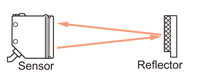 |
| With polarizing filters | It enables detection of even a specular object by attachment of polarizing filters to the emitting and the receiving parts. (Refer to "Principles of particular optical sensing systems")
|
 |
| Transparent object detection | The specially devised optical system enables detection of even a transparent object.
|
|
Reflective
| Type | Outline and Features | |
|---|---|---|
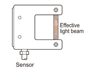
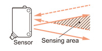
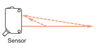
| Diffuse reflective | Emits a beam onto the object and detects the object by receiving the beam reflected from the object surface.
|
 |
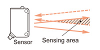
| Convergent reflective | Detects an object in the area where the emitting and the receiving envelopes overlap. A spot-beam type sensor detects an object at just the point where these envelopes cross over.
|
 |
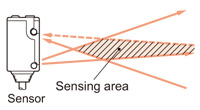
| Adjustable range reflective | Detects an object in the area where the emitting and the receiving envelopes overlap. A spot-beam type sensor detects an object at just the point where these envelopes cross over.
|
 |
| Adjustable range reflective | Emits a spot beam onto an object and senses the difference in the reflected beam angle. (Refer to "Principles of particular optical sensing systems")
|
 |
| Mark sensing | Projects a spot-beam on the target color, and identifies the color by sensing the amount of reflected beam and the relative ratio among color components. [FZ-10 series and LX-100 series (when the color mode is set)] Or projects a spot-beam on an object, and identifies the color by the proportion of the amount of light received (contrast), not by the difference in the amount of the reflected beam. [LX-100 series (when the mark mode is set)]
|
 |
(3) Classification by beam source
| Type | Features |
|---|---|
| Infrared beam | Intense beam offers long sensing range Unable to expose films |
| Red beam | Suitable for color mark sensing Visible We also have laser sensors that used semiconductor lasers instead of LEDs. |
| Green beam | Suitable for color mark sensing Suitable for minute detection because of a high beam damping ratio. Visible |
| Blue beam | Suitable for color mark sensing Suitable for minute detection because of a high beam damping ratio. Visible |
| Three color beam (Red, Green, Blue) |
Color detected by resolving it into three color components Fine color discrimination possible |
Color combinations that can be discerned during mark sensing
| Mark color | White | Yellow | Orange | Red | Green | Blue | Black |
|---|---|---|---|---|---|---|---|
| Background color | |||||||
| White | - | (B) | (B) | (G)(B) | (R)(G)(B) | (R)(G)(B) | (R)(G)(B) |
| Yellow | (B) | - | (G) | (G) | (R)(G)(B) | (R)(G)(B) | (R)(G)(B) |
| Orange | (B) | (G) | - | (G)(B) | (R)(G)(B) | (R)(G)(B) | (R)(G)(B) |
| Red | (G)(B) | (G) | (G)(B) | - | (R) | (R)(B) | (R)(B) |
| Green | (R)(G)(B) | (R)(G)(B) | (R)(G)(B) | (R) | - | (B) | (B) |
| Blue | (R)(G)(B) | (R)(G)(B) | (R)(G)(B) | (R)(B) | (B) | - | (B) |
| Black | (R)(G)(B) | (R)(G)(B) | (R)(G)(B) | (R)(B) | (B) | (B) | - |
| (R) | : | Red LED type |
|---|---|---|
| (G) | : | Green LED type |
| (B) | : | Blue LED type |
(4) Classification by output circuit
ON / OFF output
| Type | Outline and Features | ||||||||||||
|---|---|---|---|---|---|---|---|---|---|---|---|---|---|
| NPN open-collector transistor |
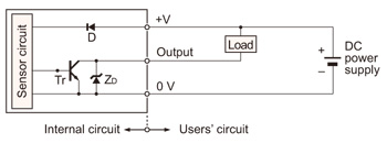
Symbols
|
||||||||||||
| PNP open-collector transistor |
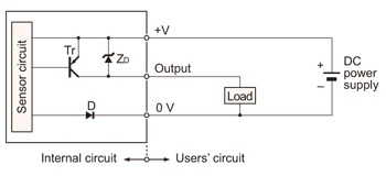
Symbols
|
||||||||||||
| DC 2-wire |
Symbols
|
||||||||||||
| NPN transistor universal |
Symbols
|
||||||||||||
| Relay contact |
|
Analog output
| Type | Outline and Features | ||||||
|---|---|---|---|---|---|---|---|
| Analog voltage |
Symbols
|
||||||
| Analog current (Monitor current) |
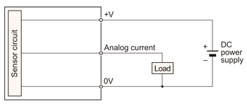
|
Related Products
Download
- photoelectric_e.pdf

|
BY EMAIL


Requests to customers (Automation Control Components & Industrial Device) [Excluding specific product]
Requests to customers (Automation Control Components & Industrial Device) [For specific product]
Requests to customers (FA Sensors & Components [Excluding motors])
Requests to customers (Dedicated to industrial motors)
- COMPONENTS & DEVICES
- FA SENSORS & COMPONENTS
- Fiber Sensors
- Photoelectric Sensors / Laser Sensors
- Micro Photoelectric Sensors
- Light Curtains / Safety Components
- Area Sensors
- Inductive Proximity Sensors
- Particular Use Sensors
- Sensor Options
- Wire-Saving Systems
- Programmable Controllers / Interface Terminal
- Human Machine Interface
- Pressure Sensors / Flow Sensors
- Measurement Sensors
- Static Control Devices
- Laser Markers / 2D Code Readers
- Machine Vision System
- Energy Management Solutions
- Timers / Counters / FA Components
- MOTORS
![]()