
 Business
> Industrial Devices
> Automation Controls Top
> Components & Devices
> Connectors
> High Current Connectors
> P4SP(0.4mm pitch)
> Dimensions
Business
> Industrial Devices
> Automation Controls Top
> Components & Devices
> Connectors
> High Current Connectors
> P4SP(0.4mm pitch)
> Dimensions
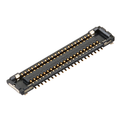
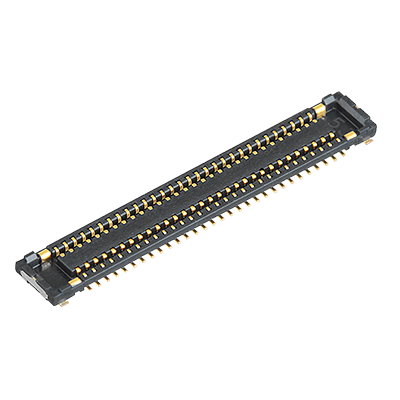
P4SP(0.4mm pitch)
Realized space savings for power line, and increased design flexibility
|
 |
 |

Features
- ●
Capable of Max. 5 A for power
Rated current 1 A/pin (for power) 0.5 A/pin (for signal), Total: Max. 12 A - ●
Any terminal can be applied for power terminal
- ●
Low contact resistance: Max. 40 mΩ
- ●
High speed transmission of 10Gbps is available
Applications
- ●
DSC, mobile devices and industrial equipment
-
Lineup
-
 A35P(0.35mm pitch)
Space savings and design flexibility are available by supporting high current rating
A35P(0.35mm pitch)
Space savings and design flexibility are available by supporting high current rating
-
 A35UH(0.35mm pitch)
Supports 5 A for power terminal. Reduce number of pins is available.
A35UH(0.35mm pitch)
Supports 5 A for power terminal. Reduce number of pins is available.
-
 B01
Achieved high current capacity ( 6 A ) and high reliability with low profile of 0.6 mm/0.8 mm
B01
Achieved high current capacity ( 6 A ) and high reliability with low profile of 0.6 mm/0.8 mm
-
 B02
Low 0.7 mm profile, high current capacity ( 10 A ) , 4 signal pins
B02
Low 0.7 mm profile, high current capacity ( 10 A ) , 4 signal pins
-
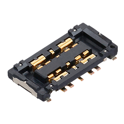
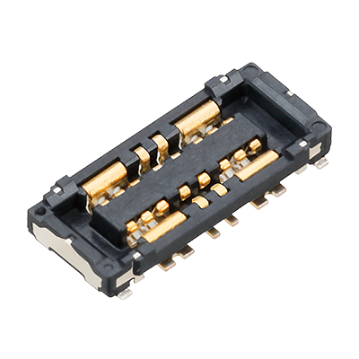
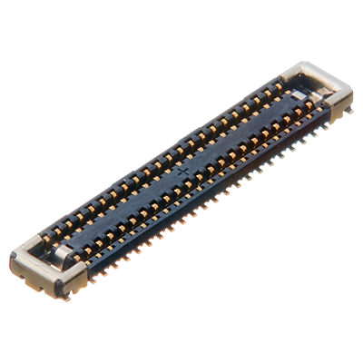
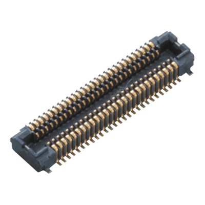 P4SP(0.4mm pitch)
Realized space savings for power line, and increased design flexibility
P4SP(0.4mm pitch)
Realized space savings for power line, and increased design flexibility
-
 R35(0.35mm pitch)
Supports 5 A for power terminal The ultra-small ( width 1.7mm ) high mating force connector
R35(0.35mm pitch)
Supports 5 A for power terminal The ultra-small ( width 1.7mm ) high mating force connector
-
- CAD data Catalogs/Datasheets
- FAQ
|
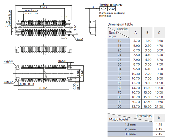
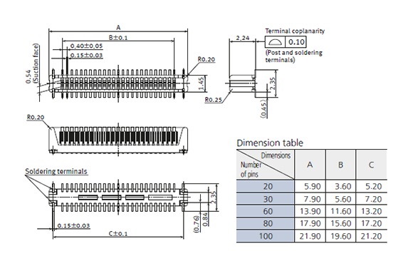
- unit: mm
1.Socket (Mated height: 1.5 mm • 2.5 mm • 3.0 mm)
|
|

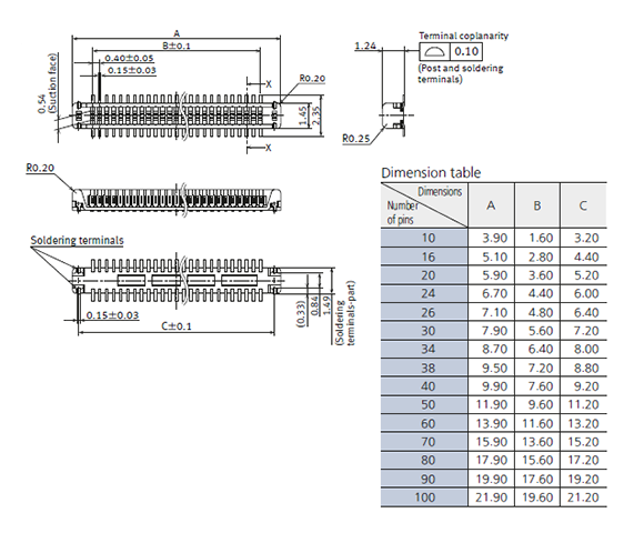
2.Header (Mated height: 1.5 mm • 2.5 mm)
|
|
3.Header (Mated height: 3.0 mm)
|

|
4.Socket and Header are mated
|
5.Embossed Tape Dimensions
- Unit: mm
Specifications for taping
In accordance with JIS C 0806-3:1999. However, not applied to the mounting-hole pitch of some connectors.
Specifications for the plastic reel
In accordance with EIAJ ET-7200B.
Dimension table (Unit: mm)
| Type/Mated height | Number of pins | Type of taping | A | B | C | D | Quantity per reel |
|---|---|---|---|---|---|---|---|
| Common for sockets and headers 1.5mm • 2.5mm • 3.0mm |
10 to 24 | Tape I | 16.0 | − | 7.5 | 17.4 | 3,000 |
| 26 to 70 | Tape I | 24.0 | − | 11.5 | 25.4 | 3,000 | |
| 80 to 100 | Tape II | 32.0 | 28.4 | 14.2 | 33.4 | 3,000 |
Connector orientation with respect to embossed tape feeding direction
There is no indication on this product regarding top-bottom or left-right orientation.
|
Related Information
BY EMAIL
- U.S.A.
- +1-800-344-2112
- Europe
- +49-89-45354-1000
- China
- +86-10-59255988
- Singapore
- +65-6299-9181


Requests to customers (Automation Control Components & Industrial Device) [Excluding specific product]
Requests to customers (Automation Control Components & Industrial Device) [For specific product]
Requests to customers (FA Sensors & Components [Excluding motors])
Requests to customers (Dedicated to industrial motors)
- COMPONENTS & DEVICES
- FA SENSORS & COMPONENTS
- Fiber Sensors
- Photoelectric Sensors / Laser Sensors
- Micro Photoelectric Sensors
- Light Curtains / Safety Components
- Area Sensors
- Inductive Proximity Sensors
- Particular Use Sensors
- Sensor Options
- Wire-Saving Systems
- Programmable Controllers / Interface Terminal
- Human Machine Interface
- Pressure Sensors / Flow Sensors
- Measurement Sensors
- Static Control Devices
- Laser Markers / 2D Code Readers
- Machine Vision System
- Energy Management Solutions
- Timers / Counters / FA Components
- MOTORS
![]()