AUTOMATION
CONTROLS

Search
Discontinued
Products


Relays Cautions for Use

Mechanical relays Selection Guide

A relay may be subjected to a variety of ambient conditions during actual use resulting in unexpected failure. Therefore, testing over a practical range under actual operating conditions is necessary.

Application considerations should be reviewed and determined for proper use of the relay.

Since the reference data in the catalog is the result of the evaluation / measurement of the samples, it is not guaranteed value.

SAFETY PRECAUTIONS

  • Use that exceeds the specification ranges such as the coil rating, contact rating and switching life should be absolutely avoided. Doing so may lead to abnormal heating, smoke, and fire.
  • Never touch live parts when power is applied to the relay. Doing so may cause electrical shock. When installing, maintaining, or troubleshooting a relay (including connecting parts such as terminals and sockets) be sure that the power is turned off.
  • When connection terminals, please follow the internal connection diagrams in the catalog to ensure that connections are done correctly. Be warned that an incorrect connection may lead to unexpected operation error, abnormal heating, and fire.
  • If the possibility exists that faulty adhesion or contact could endanger assets or human life, take double safety precautions and make sure that operation is foolproof.

Method of Determining Specifications

In order to use the relays properly, the characteristics of the selected relay should be well known, and the conditions of use of the relay should be investigated to determine whether they are matched to the environmental conditions, and at the same time, the coil conditions, contact conditions, and the ambient conditions for the relay that is actually used must be sufficiently known in advance.
In the table below, a summary has been made of the points of consideration for relay selection. It may be used as a reference for investigation of items and points of caution.

Specification item Consideration points regarding selection
Coil a) Rating
b) Operate voltage/current
c) Release voltage/current
d) Maximum applied voltage/current
e) Coil resistance
f) Impedance
g) Temperature rise
・ Select relay with consideration for power source ripple.
・ Give sufficient consideration to ambient temperature, for the coil temperature rise and hot start.
・ When used in conjunction with semiconductors, additional attention to the application should be taken.
・ Be careful of voltage drops when starting up.
Contacts a) Contact arrangement
b) Contact rating
c) Contact material
d) Life
e) Contactresistance
・ It is desirable to use a standard product with more than the required number of contacts.
・ It is beneficial to have the relay life balanced with the life of the device it is used in.
・ Is the contact material matched to the type of load?
It is necessary to take care particularly with low level load.
・ The rated life may become reduced when used at high temperatures.
The Life should be verified in the actual atmosphere used.
・ Depending on the circuit, the relay drive may synchronize with the AC load.
As this will cause a drastic shortening of life should be verified with the actual machine.
Operate time a) Operate time
b) Release time
c) Bounce time
d) Switching frequency
・ The change of ambient temperature or applied voltage affects the operate/release/bounce time.
・ It is beneficial to make the bounce time short for sound circuits and similar applications.
・ The frequency of operation affects the expected life.
Mechanical characteristics a) Vibration resistance
b) Shock resistance
c) Ambient temperature
d) Life
・ Give consideration to performance under vibration and shock in the use location.
・ A relay that uses insulated copper wire of high heat resistance if it will be used in a particularly high temperature environment.
Other items a) Dielectric strength
b) Mounting method
c) Size
d) Protective construction
・ Selection can be made for terminal connection method with plug-in type, PC board type, soldering, tab terminals, and screw fastening type.
・ For use in an adverse atmosphere, sealed construction type should be selected.
・ When used in adverse environments, use the sealed type.
・ Are there any special conditions?

Basics on Relay Handling

  • To maintain initial performance, care should be taken to avoid dropping or hitting the relay.
  • Under normal use, the relay is designed so that the case will not detach. To maintain initial performance, the case should not be removed. Relay characteristics cannot be guaranteed if the case is removed.
  • Use of the relay in an atmosphere at standard temperature and humidity with minimal amounts of dust, SO2, H2S, or organic gases is recommended. For installation in adverse environments, plastic sealed type should be selected. Please avoid the use of siliconbased resins near the relay, because doing so may result in contact failure. (This applies to plastic sealed type relays, too.)
  • Care should be taken to observe correct coil polarity (+, –) for polarized relays.
  • Proper usage requires that the rated voltage be impressed on the coil. Use rectangular waves for DC coils and sine waves for AC coils.
  • Be sure the coil impressed voltage does not continuously exceed the maximum allowable voltage.
  • The rated switching power and life are given only as guides. The physical phenomena at the contacts and contact life greatly vary depending on the type of load and the operating conditions. Therefore, be sure to carefully check the type of load and operating conditions before use.
  • Do not exceed the usable ambient temperature values listed in the catalog.
  • Use the flux-resistant type or sealed type if automatic soldering is to be used.
  • Although the environmentally sealed type relay (plastic sealed type,etc.) can be cleaned, avoid immersing the relay into cold liquid (such as cleaning solvent) immediately after soldering. Doing so may deteriorate the sealing performance.
    Surface-mount terminal type relay is sealed type and it can be cleaned by immersion. Use pure water or alcohol-based cleaning solvent.
    Cleaning with the boiling method is recommended (The temperature of cleaning liquid should be 40°C or lower). Avoid ultrasonic cleaning on relays. Use of ultrasonic cleaning may cause breaks in the coil or slight sticking of the contacts due to the ultrasonic energy.
  • Avoid bending terminals, because it may cause malfunction.
  • As a guide, use a Faston mounting pressure of 40 to 70N {4 to 7kgf}for relays with tab terminals.
  • For proper use, read the main text for details.

Return to top

Precautions Regarding Coil Input

Apply the rated voltage to the coil for accurate relay operation.
Although the relay will work if the voltage applied exceeds the operate voltage, it is required that only the rated voltage be applied to the coil out of consideration for changes in coil resistance, etc., due to differences in power supply type, voltage fluctuations, and rises in temperature. Also, caution is required, because problems such as layer shorts and burnout in the coil may occur if the voltage applied exceeds the maximum that can be applied. The following section contains precautions regarding coil input. Please refer to it in order to avoid problems.

Basic Precautions Regarding Coil

AC operation type

For the operation of AC relays, the power source is almost always a commercial frequency (50 or 60 Hz) with standard voltages of 6, 12, 24, 48, 100, and 200 V AC. Because of this, when the voltage is other than the standard voltage, the product is a special order item, and the factors of price, delivery, and stability of characteristics may create inconveniences. To the extent that it is possible, the standard voltages should be selected.
Also, in the AC type, shading coil resistance loss, magnetic circuit eddy current loss, and hysteresis loss exit, and because of lower coil efficiency, it is normal for the temperature rise to be greater than that for the DC type.
Furthermore, because humming occurs when below the operate voltage and when above the rated voltage, care is required with regard to power source voltage fluctuations.
For example, in the case of motor starting, if the power source voltage drops, and during the humming of the relay, if it reverts to the restored condition, the contacts suffer a burn damage and welding, or the selfmaintaining condition may be lost.
For the AC type, there is an inrush current during the operation time (for the separated condition of the armature, the impedance is low and a current greater than rated current flows; for the adhered condition of the armature, the impedance is high and the rated value of current flows), and because of this, for the case of several relays being used in parallel connection, it is necessary to give consideration to power consumption.

DC operation type

For the operation of DC relays, standards exist for power source voltage and current, with DC voltage standards set at 5, 6, 12, 24, 48, and 100 V, but with regard to current, the values as expressed in catalogs in milliamperes of pick-up current.
However, because this value of pick-up current is nothing more than a guarantee of just barely moving the armature, the variation in energizing voltage and resistance values ,and the increase in coil resistance due to temperature rise, must be given consideration for the worst possible condition of relay operation, making it necessary to consider the current value as 1.5 to 2 times the pick-up current. Also, because of the extensive use of relays as limit devices in place of meters for both voltage and current, and because of the gradual increase or decrease of current impressed on the coil causing possible delay in movement of the contacts, there is the possibility that the designated control capacity may not be satisfied. Thus it is necessary to exercise care. The DC type relay coil resistance varies due to ambient temperature as well as to its own heat generation to the extent of about 0.4%/°C, and accordingly, if the temperature increases, because of the increase in pick-up and drop-out voltages, care is required. (However, for some polarized relays, this rate of change is considerably smaller.)

Power Source for Coil Input

Power source for AC input

In order to have stable operation of the relay, the energizing voltage should be basically within the range of +10%/-15% of the rated voltage. However, it is necessary that the waveform of the voltage impressed on the coil be a sine wave. There is no problem if the power source is commercially provided power, but when a stabilized AC power source is used, there is a waveform distortion due to that equipment, and there is the possibility of abnormal overheating. By means of a shading coil for the AC coil, humming is stopped, but with a distorted waveform, that function is not displayed.
*Fig. 1 below shows an example of waveform distortion.
If the power source for the relay operating circuit is connected to the same line as motors, solenoids, transformers, and other loads, when these loads operate, the line voltage drops, and because of this the relay contacts suffer the effect of vibration and subsequent burn damage.
In particular, if a small type transformer is used and its capacity has no margin of safety, when there is long wiring, or in the case of household used or small sales shop use where the wiring is slender, it is necessary to take precautions because of the normal voltage fluctuations combined with these other factors. When trouble develops, a survey of the voltage situation should be made using a synchroscope or similar means, and the necessary counter-measures should be taken, and together with this determine whether a special relay with suitable excitation characteristics should be used, or make a change in the DC circuit as shown in Fig. 2 in which a capacitor is inserted to absorb the voltage fluctuations.
In particular, when a magnetic switch is being used, because the load becomes like that of a motor, depending upon the application, separation of the operating circuit and power circuit should be tried and investigated.

Power Source for DC Input

We recommend that the voltage applied to both ends of the coil in DC type relays be within ±5% of the rated coil voltage.
As a power source for the DC type relay, a battery or either a half wave or full wave rectifier circuit with a smoothing capacitor is used. The characteristics with regard to the operate voltage of the relay will change depending upon the type of power source, and because of this, in order to display stable characteristics, the most desirable method is perfect DC.
In the case of ripple included in the DC power source, particularly in the case of half wave rectifier circuit with a smoothing capacitor, if the capacity of the capacitor is too small, due to the influence of the ripple, humming develops and an unsatisfactory condition is produced.
With the actual circuit to be used, it is absolutely necessary to confirm the characteristics.
It is necessary to give consideration to the use of a DC power source with less than a 5% ripple. Also ordinarily the following must be given thought.

  • 1.For the hinge type relay, a half wave rectifier cannot be used, alone unless you use a smoothing capacitor. The ripple and the characteristics must be evaluated for proper usage.
  • 2.For the hinge type relay, there are certain applications that may or maynot use the full wave rectifier on it’s own. Please check specifications with our sales office.
  • 3.Coil applied voltage and the drop in voltage
    Shown on the Fig. 4, is a circuit driven by the same power supply (battery, etc.) for both the coil and contact.
    Electrical life will be affected by the drop in voltage in the coil when load is turned on.
    Please verify that the actual voltage is applied to the coil at the actual load.

Maximum Applied Voltage and Temperature Rise

Proper usage requires that the rated voltage be impressed on the coil.
Note, however, that if a voltage greater than or equal to the maximum applied voltage is impressed on the coil, the coil may burn or its layers short due to the temperature rise.
Furthermore, do not exceed the usable ambient temperature range listed in the catalog.

Maximum applied voltage

In addition to being a requirement for relay operation stability, the maximum applied voltage is an important constraint for the prevention of such problems as thermal deterioration or deformity of the insulation material, or the occurrence of fire hazards.

Operate voltage change due to coil temperature rise (hot start)

In DC relays, after continuous passage of current in the coil, if the current is turned OFF, then immediately turned ON again, due to the temperature rise in the coil, the operate voltage will become somewhat higher. Also, it will be the same as using it in a higher temperature atmosphere. The resistance/temperature relationship for copper wire is about 0.4% for 1°C, and with this ratio the coil resistance increases. That is, in order to operate of the relay, it is necessary that the voltage be higher than the operate voltage and the operate voltage rises in accordance with the increase in the resistance value.
However, for some polarized relays, this rate of change is considerably smaller.

Coil Applied Voltage and Operate Time

In the case of AC operation, there is extensive variation in operate time depending upon the point in the phase at which the switch is turned ON for coil excitation, and it is expressed as a certain range, but for miniature types it is for the most part 1/2 cycle. However, for the somewhat large type relay where bounce is large, the operate time is 7 to 16ms, with release time in the order of 9 to 18ms Also, in the case of DC operation, to the extent of large coil input, the operating time is rapid, but if it is too rapid, the "Form A" contact bounce time is extended. Please be warned that load conditions (in particular when inrush current is large or load is close to the load rating) may cause the working life to shorten and slight welding.

Stray Circuits (Bypass Circuits)

In the case of sequence circuit construction, because of bypass flow or alternate routing, it is necessary to take care not to have erroneous operation or abnormal operation. To understand this condition while preparing sequence circuits, as shown in Fig. 5, with 2 lines written as the power source lines, the upper line is always ⊕ and the lower line ⊖ (when the circuit is AC, the same thinking applies). Accordingly the ⊕ side is necessarily the side for making contact connections (contacts for relays, timers and limit switches, etc.), and the ⊖ side is the load circuit side (relay coil, timer coil, magnet coil, solenoid coil, motor, lamp, etc.).
Fig. 6 shows an example of stray circuits.
In Fig. 6 (a), with contacts A, B, and C closed, after relays R1, R2, and R3 operate, if contacts B and C open, there is a series circuit through A, R1, R2, and R3, and the relays will hum and sometimes not be restored to the drop out condition.
The connections shown in Fig. 6 (b) are correctly made. In addition, with regard to the DC circuit, because it is simple by means of a diode to prevent stray circuits, proper application should be made.

Gradual Increase of Coil Applied Voltage and Suicide Circuit

When the voltage applied on the coil is increased slowly, the relay transferring operation is unstable, the contact pressure drops, contact bounce increases, and an unstable condition of contact occurs. This method of applying voltage to the coil should not be used, and consideration should be given to the method of impressing voltage on the coil (use of switching circuit). Also, in the case of latching relays, using self “Form B” contacts, the method of self coil circuit for complete interruption is used, but because of the possibility of trouble developing, care should be taken.
The circuit shown in Fig. 7 causes a timing and sequential operation using a reed type relay, but this is not a good example with mixture of gradual increase of impressed voltage for the coil and a sucide circuit. In the timing portion for relay R1, when the timing times out, chattering occurs causing trouble. In the initial test (trial production), it shows favorable operation, but as the number of operations increases, contact blackening (carbonization) plus the chattering of the relay creates instability in performance.

Phase Synchronization in AC Load Switching

If switching of the relay contacts is synchronized with the phase of the AC power, reduced electrical life, welded contacts, or a locking phenomenon (incomplete release) due to contact material transfer may occur. Therefore, check the relay while it is operating in the actual system. When driving relays with timers, micro computers and thyristors, etc., there may be synchronization with the power supply phase.

Erroneous Operation Due to Inductive Interference

For long wire runs, when the line for the control circuit and the line for electric power use a single conduit, induction voltage, caused by induction from the power line, will be applied to the operation coil regardless of whether or not the control signal is off. In this case the relay and timer may not revert. Therefore, when wiring spans a long distance please remember that along with inductive interference, connection failure may be caused by a problem with distribution capacity or the device might break down due to the influenced of externally caused surges, such as that caused by lightning.

Long Term Current Carrying

A circuit that will be carrying a current continuously for long periods without relay switching operation. (circuits for emergency lamps, alarm devices and error inspection that, for example, revert only during malfunction and output warnings with form B contacts)
Continuous, long-term current to the coil will facilitate deterioration of coil insulation and characteristics due to heating of the coil itself. For circuits such as these, please use a magnetic-hold type latching relay. If you need to use a single stable relay, use a sealed type relay that is not easily affected by ambient conditions and make a failsafe circuit design that considers the possibility of contact failure or disconnection.

Usage With Infrequent Switching

Please carry out periodic contact conductivity inspections when the frequency of switching is once or fewer times per month.
When no switching of the contacts occurs for long periods, organic membrane may form on the contact surfaces and lead to contact instability.

Regarding Electrolytic Corrosion of Coils

In the case of comparatively high voltage coil circuits, when such relays are used in high temperature and high humidity atmospheres or with continuous passage of current, Electrocorrosion may occur in the coil and the wire may be disconnected. Because of the possibility of open circuits occurring, attention should be given to the following points.

  • 1.The ⊕ side of the power source should be connected to the chassis. (Refer to Fig. 9) (Common to all relays)
  • 2.In the case where unavoidably the ⊖ side is grounded, or in the case where grounding is not possible.
    (1) Insert the contacts (or switch) in the ⊕ side of the power source. (Refer to Fig. 10) (Common to all relays)
    (2) When a grounding is not required, connect the ground terminal to the ⊕ side of the coil. (Refer to Fig. 11)
  • 3.When the ⊖ side of the power source is grounded, always avoid interting the contacts (and switches) in the ⊖ side. (Refer to Fig. 12) (Common to all relays)

Return to top

Precautions Regarding Contact

Contact

The contacts are the most important elements of relay construction. Contact performance conspicuously influenced by contact material, and voltage and current values applied to the contacts (in particular, the voltage and current waveforms at the time of application and release), the type of load, frequency of switching, ambient atmosphere, form of contact, contact switching speed, and of bounce.
Because of contact transfer, welding, abnormal wear, increase in contact resistance, and the various other damages which bring about unsuitable operation, the following items require full investigation.

*We recommend that you verify with one of our sales offices.

Basic Precautions Regarding Contact

Voltage

When there is inductance included in the circuit, a rather high counter emf is generated as a contact circuit voltage, and since, to the extent of the value of that voltage, the energy applied to the contacts causes damage with consequent wear of the contacts, and transfer of the contacts, it is necessary to exercise care with regard to control capacity. In the case of DC, there is no zero current point such as there is with AC, and accordingly, once a cathode arc has been generated, because it is difficult to quench that arc, the extended time of the arc is a major cause. In addition, due to the direction of the current being fixed, the phenomenon of contact shift, as noted separately below, occurs in relation to the contact wear. Ordinarily, the approximate control capacity is mentioned in catalogs or similar data sheets, but this alone is not sufficient.
With special contact circuits, for the individual case, the maker either estimates from the past experience or makes test on each occasion. Also, in catalogs and similar data sheets, the control capacity that is mentioned is limited to resistive load, but this shows the class of relay and ordinarily it is proper to think of current capacity as that for 125 V AC circuits. Minimum applicable loads are given in the catalog; however, these are only provided as a guide to the lower limit that the relay is able to switch and are not guaranteed values. The level of reliability of these values depends on switching frequency, ambient conditions, change in the desired contact resistance, and the absolute value. Please use relays with AgPd contacts when minute analog load control or contact resistance no higher than 100 mΩ is desired (for measurement and wireless applications, etc.).

Current

The current at both the closing and opening time of the contact circuit exerts important influence. For example, when the load is either a motor or a lamp, to the extent of the inrush current at the time of closing the circuit, wear of the contacts, and the amount of contact transfer increase, and contact welding and contact transfer make contact separation impossible.
Generally the contact resistance becomes more stable with higher carry current. If the expected reliability level cannot be obtained even when the load exceeds the minimum applicable load, consider increasing the carry current based on the evaluation of the actual operating environment.

Characteristics of Common Contact Materials

Characteristics of contact materials are given below. Refer to them when selecting a relay.

Contact Material Ag
(silver)
Electrical conductivity and thermal conductivity are the highest of all metals. Exhibits low contact resistance, is inexpensive and widely used. A disadvantage is it easily develops a sulfide film in a sulfide atmosphere. Care is required at low voltage and low current levels.
AgSnO2
(silver-tin oxide)
Exhibits superior welding resistance; however, as with Ag, it easily develops a sulfide film in a sulfide atmosphere.
AgW
(silver-tungsten)
Hardness and melting point are high, arc resistance is excellent, and it is highly resistant to material transfer. However, high contact pressure is required. Furthermore, contact resistance is relatively high and resistance to corrosion is poor. Also, there are constraints on processing and mounting to contact springs.
AgNi
(silver-nickel)
Equals the electrical conductivity of silver. Excellent arc resistance.
AgPd
(silver-palladium)
Exhibits high resistance to corrosion and sulfidation at room temperature; however, in low-level circuits, it easily absorbs organic gases and forms polymers. Gold cladding or other measures should be used to prevent such polymer buildup.
Surface Finish Rh plating
(rhodium)
Combines perfect corrosion resistance and hardness. As plated contacts, used for relatively light loads. In an organic gas atmosphere, care is required as polymers may develop. Therefore, it is used in hermetic seal relays (reed relays, etc.) .
Au clad
(gold clad)
Au with its excellent corrosion resistance is pressure welded onto a base metal. Special characteristics are uniform thickness and the nonexistence of pinholes. Greatly effective especially for low level loads under relatively adverse atmospheres. Often difficult to implement clad contacts in existing relays due to design and installation.
Au plating
(gold plating)
Similar effect to Au cladding. Depending on the plating process used, supervision is important as there is the possibility of pinholes and cracks. Relatively easy to implement gold plating in existing relays.
Au flash plating
(gold thin-film plating)
0.1 to 0.5 μm
Purpose is to protect the contact base metal during storage of the switch or device with built-in switch. However, a certain degree of contact stability can be obtained even when switching loads.

Contact Protection

Counter EMF

When switching inductive loads with a DC relay such as relay sequence circuits, DC motors, DC clutches, and DC solenoids, it is always important to absorb surges (e.g. with a diode) to protect the contacts.
When these inductive loads are switched off, a counter emf of several hundred to several thousand volts develops which can severely damage contacts and greatly shorten life. If the current in these loads is relatively small at around 1 A or less, the counter emf will cause the ignition of a glow or arc discharge. The discharge decomposes organic matter contained in the air and causes black deposits (oxides, carbides) to develop on the contacts, this may result in contact failure.

Example of counter emf and actual measurement

In Fig. 13 (a), a counter emf (e = –L di/dt) with a steep waveform is generated across the coil with the polarity shown in Fig. 13 (b) at the instant the inductive load is switched off. The counter emf passes through the power supply line and reaches both contacts.
Generally, the critical dielectric breakdown voltage at standard temperature and pressure in air is about 200 to 300 volts. Therefore, if the counter emf exceeds this, discharge occurs at the contacts to dissipate the energy (1/2Li2) stored in the coil. For this reason, it is desirable to absorb the counter emf so that it is 200 V or less.

Material Transfer Phenomenon

Material transfer of contacts occurs when one contact melts or boils and the contact material transfers to the other contact. As the number of switching operations increases, uneven contact surfaces develop such as those shown in Fig. 14. After a while, the uneven contacts lock as if they were welded together. This often occurs in circuits where sparks are produced at the moment the contacts “make” such as when the DC current is large for DC inductive or capacitive loads or when the inrush current is large (several amperes or several tens of amperes).
Contact protection circuits and contact materials resistant to material transfer such as AgSnO2, AgW or AgCu are used as countermeasures. Generally, a concave formation appears on the cathode and a convex formation appears on the anode. For DC capacitive loads (several amperes to several tens of amperes), it is always necessary to conduct actual confirmation tests.

Contact Protection Circuit

Use of contact protective devices or protection circuits can suppress the counter emf to a low level. However, note that incorrect use will result in an adverse effect. Typical contact protection circuits are given in the table below.
(G: Good, NG: No Good, C: Care)

Circuit Application Features/Others Devices Selection
AC DC
CR circuit C* G If the load is a timer, leakage current flows through the CR circuit causing faulty operation.

* If used with AC voltage, be sure the impedance of the load is sufficiently smaller than that of the CR circuit

If the load is a relay or solenoid, the release time lengthens. It is effective if CR is connected between the loads when the power supply voltage is between 24 V and 48 V.
It is effective if CR is connected between the contacts when the power supply voltage is between 100 V and 200 V.
It may be more effective to connect between contacts than between loads, especially in high voltage areas where arcing cutoff capability between contacts is a concern.
As a guide in selecting C and R,
C: 0.5 to 1 μF per 1 A contact current
R: 0.5 to 1 Ω per 1 V contact voltage
Values vary depending on the properties of the load and variations in relay characteristics.
Capacitor "C" acts to suppress the discharge the moment the contacts open.
Resistor "R" acts to limit the current when the power is turned on the next time.
Check with the actual machine. Use a capacitor "C" with a breakdown voltage of 200 to 300 V. Use AC type capacitors (non-polarized) for AC circuits.
G G
Diode circuit NG G The diode connected in parallel causes the energy stored in the coil to flow to the coil in the form of current and dissipates it as joule heat at the resistance component of the inductive load. This circuit further delays the release time compared to the CR circuit. (2 to 5 times the release time listed in the catalog) Use a diode with a reverse breakdown voltage at least 10 times the circuit voltage and a forward current at least as large as the load current. In electronic circuits where the circuit voltages are not so high, a diode can be used with a reverse breakdown voltage of about 2 to 3 times the power supply voltage.
Diode and zener diode circuit NG G Effective when the release time in the diode circuit is too long. Use a zener diode with a zener voltage about the same as the power supply voltage.
Varistor circuit G G Using the stable voltage characteristics of the varistor, this circuit prevents excessively high voltages from being applied across the contacts.
This circuit also slightly delays the release time.
It is effective if Varistor is connected between the loads when the power supply voltage is between 24 V and 48 V.
It is effective if Varistor is connected between the contacts when the power supply voltage is between 100 V and 200 V. It may be more effective to connect between contacts than between loads, especially in high voltage areas where arcing cutoff capability between contacts is a concern.
-

Avoid using the protection circuits shown in the figures below. Although DC inductive loads are usually more difficult to switch than resistive loads, use of the proper protection circuit will raise the characteristics to that for resistive loads.

Although extremely effective in arc suppression as the contacts open, the contacts are susceptible to welding since energy is stored in C when the contacts open and discharge current flows from C when the contacts close.

Although extremely effective in arc suppression as the contacts open, the contacts are susceptible to welding since charging current flows to C when the contacts close.

Mounting the Protective Device

In the actual circuit, it is necessary to locate the protective device (diode, resistor, capacitor, varistor, etc.) in the immediate vicinity of the load or contact. If located too far away, the effectiveness of the protective device may diminish. As a guide, the distance should be within 50 cm.

DC Load Guidelines

In case the relay is used as a DC high voltage switch, the final failure mode may be uninterruptible.
In the event that the power supply cannot be cut off, in the worst case, the fire may spread to the surrounding area. Therefore, configure the power supply so that it can be turned off within one second. Also, consider a fail safe circuit for your equipment.
Use a varistor to absorb the surge of the coil.
If a diode is used, the contact separation speed will be slow and the cutoff performance will be degraded.

[ Recommended Varistor ]
Energy tolerance: 1 J or more
varistor voltage: 1.5 times or more of the rated coil voltage

When using an inductive load (L load) with L/R > 1 ms, take surge absorption measures in parallel with the inductive load.

Abnormal corrosion during high frequency switching of DC loads (spark generation)

If, for example, a DC valve or clutch is switched at a high frequency, blue-green rust may develop. This occurs from the reaction of nitrogen and oxygen in the air when sparks (arc discharge) are generated during switching. Therefore, care is required in circuits where sparks are generated at a high frequency.

Cautions on Use Related to Contacts

Connection of load and contacts

Connect the load to one side of the power supply as shown in Fig. 15 (a). Connect the contacts to the other side.
This prevents high voltages from developing between contacts. If contacts are connected to both side of the power supply as shown in Fig. 15 (b), there is a risk of shorting the power supply when relatively close contacts short.

Dummy Resistor

Since voltage levels at the contacts used in low current circuits (dry circuits) are low, poor conduction is often the result. One method to increase reliability is to add a dummy resistor in parallel with the load to intentionally raise the load current reaching the contacts.

Shorts Between Different Electrodes

Although there is a tendency to select miniature control components because of the trend toward miniaturizing electrical control units, care must be taken when selecting the type of relay in circuits where different voltages are applied between electrodes in a multi-pole relay, especially when switching two different power supply circuits. This is not a problem that can be determined from sequence circuit diagrams. The construction of the control component itself must be examined and sufficient margin of safety must be provided especially in creepage between electrodes, space distance, presence of barrier, etc.

About Parallel Relay Connections

When multiple relays are connected in parallel, design the equipment so that the load applied to each relay is within the specified range.
(Concentration of load on one relay leads to early failure.)

Avoid circuits where shorts occur between Form A and B contacts

  • 1) The clearance between form A and B contacts in compact control components is small. The occurrence of shorts due to arcing must be assumed.
  • 2) Even if the three N.C., N.O., and COM contacts are connected so that they short, never configure a circuit that overcurrent flows or burns.
  • 3) A forward and reverse motor rotation circuit using switching of form A and B contacts must never be designed.
Bad example of Form A and B use

Type of Load and Inrush Current

The type of load and its inrush current characteristics, together with the switching frequency, are important factors which cause contact welding. Particularly for loads with inrush currents, measure the steady state and inrush current.
Then select a relay which provides an ample margin of safety. The table on the right shows the relationship between typical loads and their inrush currents.
Also, verify the actual polarity used since, depending on the relay, electrical life is affected by the polarity of COM and NO.

Type of load Inrush current
Resistive load Steady state current
Solenoid load 10 to 20 times the steady state current
Motor load 5 to 10 times the steady state current
Incandescent lamp load 10 to 15 times the steady state current
Mercury lamp load Approx. 3 times the steady state current
Sodium vapor lamp load 1 to 3 times the steady state current
Capacitive load 20 to 40 times the steady state current
Transformer load 5 to 15 times the steady state current

Load Inrush Current Wave and Time

(1) Incandescent Lamp Load

Inrush current/rated current: i/io ≒ 10 to 15 times

(2) Mercury Lamp Load
i/io ≒ 3 times

The discharge tube, transformer, choke coil, capacitor, etc., are combined in common discharge lamp circuits. Note that the inrush current may be 20 to 40 times, especially if the power supply impedance is low in the high power factor type.

(3) Fluorescent Lamp Load
i/io ≒ 5 to 10 times
(4) Motor Load
i/io ≒ 5 to 10 times
  • Conditions become more harsh if plugging or inching is performed since state transitions are repeated.
  • When using a relay to control a DC motor and brake, the on time surge current, normal current and off time brake current differ depending on whether the load to the motor is free or locked.
    In particular, with non-polarized relays, when using from B contact of from contact for the DC motor brake, mechanical life might be affected by the brake current. Therefore, please verify current at the actual load.
(5) Solenoid Load
i/io ≒ 10 to 20 times

Note that since inductance is great, the arc lasts longer when power is cut. The contact may become easily worn.

(6) Electromagnetic Contact Load
i/io ≒ 3 to 10 times
(7) Capacitive Load
i/io ≒ 20 to 40 times

When Using Long Wires

If long wires (dozens of meters or more) are to be used in a relay contact circuit, inrush current may become a problem due to the stray capacitance existing between wires. Add a resistor (approx. 10 to 50 Ω) in series with the contacts.

Electrical Life at High Temperatures

Verify at the actual use condition since electrical life may be affected by use at high temperatures.

Switching lifetime

The switching lifetime is defined under the standard test condition specified in the JIS* C 5442 standard (temperature 15 to 35°C, humidity 25 to 75%). Check this with the actual product as it is affected by the coil driving circuit, load type, activation frequency, activation phase, ambient conditions and other factors.
Also, be especially careful with loads such as those listed below.

  • (1)  When used for AC load-operation and the operating phase is synchronous. Rocking and welding can easily occur due to contact shifting.
  • (2)  During high frequency on/off operation with certain loads, arcing may occur at the contacts. This can cause fusion to Oxygen and Nitrogen gas in the air creating Nitric Acid (HNO3) which can cause corrosion to the contacts.
    Please see the following countermeasure examples:
    1. Incorporate an arc-extinguishing circuit.
    2. Lower the operating frequency
    3. Lower the ambient humidity
  • When "Dry-switching" without current conduction is used, please contact our sales representative.
    Please see the following countermeasure examples:
    Note: Dry-switching
    Dry-switching can reduce the consumption of contact material without current conduction.
    On the other hand, as the contact cleaning effect disappears, conduction failure may occur. This dry-switching condition is not recommended in applying our relay.

In the small load region, the oxide film and sulfide film produced by the atmosphere cannot be destroyed, and may affect the carrying current and switching performance.
When using the product in a small load area, check with the actual machine in the expected operating environment.

Return to top

Precautions Regarding Latching Relays

  • Latching relays are shipped from the factory in the reset state. A shock to the relay during shipping or installation may cause it to change to the set state.
    Therefore, it is recommended that the relay be used in a circuit which initializes the relay to the required state (set or reset) whenever the power is turned on.
  • Avoid impressing voltages to the set coil and reset coil at the same time.
  • Connect a diode as shown since latching may be compromised when the relay is used in the following circuits.
    - If set coils or reset coils are to be connected together in parallel, connect a diode in series to each coil. Fig. 17 (a), (b)
    - Also, if the set coil of a relay and the reset coil of another relay are connected in parallel, connect a diode to the coils in series. Fig. 17 (c)
    - If the set coil or reset coil is to be connected in parallel with an inductive load (e.g. another electromagnetic relay coil, motor, transformer, etc.), connect a diode to the set coil or reset coil in series. Fig. 17 (d)
  • Use a diode having an ample margin of safety for repeated DC reverse voltage and peak reverse voltage applications and having an average rectified current greater than or equal to the coil current.
  • Avoid applications in which conditions include frequent surges to the power supply.
  • Avoid using the following circuit since self-excitation at the contacts will inhibit the normal keep state.

■ Four-Terminal Latching Relay

In the 2-coil latching type circuit as shown below, one terminal at one end of the set coil and one terminal at one end of the reset coil are connected in common and voltages of the same polarity are applied to the other side for the set and reset operations. In this type of circuit, short 2 terminals of the relay as noted in the table below. This helps to keep the insulation high between the two winding.

Relay Type Terminal Nos.
DS 1 Form C -
2 Form C 15 & 16
ST *
SP 2 & 4
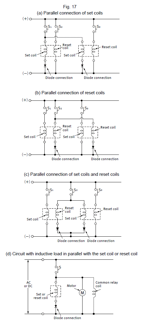
1. * ST relays are constructed so that the set coil and reset coil are separated for high insulation resistance.
2. DSP, TQ, S relays are not applicable due to polarity.

■ Minimum Pulse Width

As a guide, make the minimum pulse width in order to set or reset a latching relay at least 5 times the set time or reset time of each product and apply a rectangular-wave rated voltage. Also, please verify operation. Please inquire if you cannot obtain a pulse width of at least 5 times the set (reset) time. Also, please inquire regarding capacitor drive.

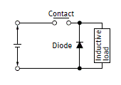
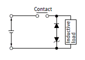
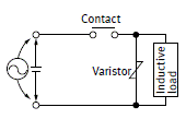
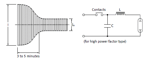
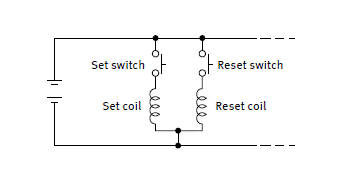
■ Two Coil Latch Induction Voltage

Each coil in a 2-coil latch relay is wound with a set coil and a reset coil on the same iron cores. Accordingly, induction voltage is generated on the reverse side coil when voltage is applied and shut off to each coil. Although the amount of induction voltage is about the same as the rated relay voltage, you must be careful of the reverse bias voltage when driving transistors.

Return to top

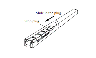
Handling Cautions for Tube Packaging

Some types of relays are supplied in tube packaging. If you remove any relays from the tube packaging, be sure to slide the stop plug at one end to hold the remaining relays firmly together so they would not move in the tube. Failing to do this may lead to the appearance and/or performance being damaged.

Return to top

Ambient Environment

Ambient Temperature and Atmosphere

Be sure the ambient temperature at the installation does not exceed the value listed in the catalog.
Furthermore, environmentally sealed types (plastic sealed type) should be considered for applications in an atmosphere with dust, sulfur gases (SO2, H2S), or organic gases.
When connecting multiple relays or when there is heat received from other equipment, Heat dissipation may be insufficient and the ambient temperature of the relay may be exceeded. After checking the temperature in the actual device, please design the circuit with sufficient thermal margin.

Silicon Atmosphere

Silicon-based substances (silicon rubber, silicon oil, silicon-based coating material, silicon caulking compound, etc.) emit volatile silicon gas. Note that when silicon is used near relay, switching the contacts in the presence of its gas causes silicon to adhere to the contacts and may result in contact failure (in plastic sealed types, too). In this case, use a substitute that is not silicon-based.

NOx Generation

When a relay is used in an atmosphere high in humidity to switch a load which easily produces an arc, the NOx created by the arc and the water absorbed from outside the relay combine to produce nitric acid. This corrodes the internal metal parts and adversely affects operation.
Avoid use at an ambient humidity of 85% R.H. or higher (at 20°C). If use at high humidity is unavoidable, consult us.
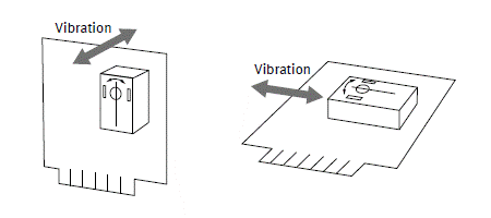
Vibration and Shock

If a relay and magnetic switch are mounted next to each other on a single plate, the relay contacts may separate momentarily from the shock produced when the magnetic switch is operated and result in faulty operation. Countermeasures include mounting them on separate plates, using a rubber sheet to absorb the shock, and changing the direction of the shock to a perpendicular angle.
Also, if vibration is always applied to the relay, evaluate the actual operating environment.
Do not use with sockets.

Influence of External Magnetic Fields

When a magnet or permanent magnet in any other large relay, transformer, or speaker is located nearby, the relay characteristics may change and faulty operations may result. The influence depends on the strength of the magnetic field and it should be checked at theinstallation.

Usage, Storage, and Transport Conditions

During usage, storage, or transportation, avoid locations subject to direct sunlight and maintain normal temperature, humidity, and pressure conditions.
The allowable specifications for environments suitable for usage, storage, and transportation are given below.

(1) Temperature

The allowable temperature range differs for each relay, so refer to the relay’s individual specifications.
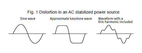
In addition, when transporting or storing relays while they are tube packaged, there are cases when the temperature may differ from the allowable range. In this situation, be sure to consult the individual specifications.with less than a 5% ripple. Also ordinarily the following must be given thought.
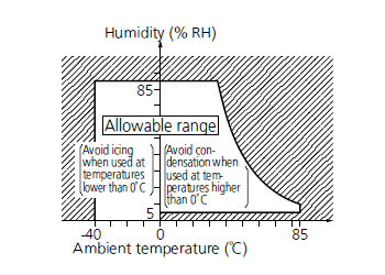
(2) Humidity

5 to 85% R.H.

  • The humidity range varies with the temperature. Use within the range indicated in the graph. (The allowable temperature depends on the relays.)

(3) Pressure

86 to 106 kPa

(4) Condensation

Condensation will occur inside the switch if there is a sudden change in ambient temperature when used in an atmosphere of high temperature and high humidity. This is particularly likely to happen when being transported by ship, so please be careful of the atmosphere when shipping. Condensation is the phenomenon whereby steam condenses to cause water droplets that adhere to the switch when an atmosphere of high temperature and humidity rapidly changes from a high to low temperature or when the switch is quickly moved from a low humidity location to one of high temperature and humidity. Please be careful because condensation can cause adverse conditions such as deterioration of insulation, coil cutoff, and rust.

(5) Icing

Condensation or other moisture may freeze on the switch when the temperatures is lower than 0°C. This may cause problems such as fixing of the movable contact, operation delay, or interference of ice between the contacts, which may interfere with contact conduction.

(6) Low temperature, low humidity

The plastic becomes brittle if the switch is exposed to a low temperature, low humidity atmosphere for long periods of time.

(7) High temperatures, high humidity

Storage for extended periods of time (including transportation periods) at high temperatures or high humidity levels or in atmospheres with organic gases or sulfide gases may cause a sulfide film or oxide film to form on the surfaces of the contacts and/or it may interfere with the functions. Check out the atmosphere in which the units are to be stored and transported.

(8) Packing format

In terms of the packing format used, make every effort to keep the effects of moisture, organic gases and sulfide gases to the absolute minimum.

(9) Storage (for signal,microwave)

Since the SMD type is sensitive to humidity it is packaged with tightly sealed anti-humidity packaging. However, when storing, please be careful of the following.

  • 1.Please use promptly once the anti-humidity pack is opened. (within 72 hours, Max. 30°C/70% R.H.).
    If left with the pack open, the relay will absorb moisture which will cause thermal stress when reflow mounting and thus cause the case to expand. As a result, the seal may break.
  • *For RE relays, after this bag is opened, the product must be used within 24 hours.
  • 2.If relays will not be used within 72 hours, please store relays in a humidity controlled desiccator or in an anti-humidity bag to which silica gel has been added.
  • *If the relay is to be soldered after it has been exposed to excessive humidity atmosphere, cracks and leaks can occur. Be sure to mount the relay under the required mounting conditions.
  • *For RE relays, after this bag is opened, the product must be used within 24 hours.
  • 3.When relays (which is packaged with humidity indicator and silica gel) meeting one of below criteria, please bake (dry) before use.
  •  (for signal)
    ・When the storage conditions specified in 1. are exceeded.
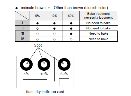
    ・When humidity indicator is in III or IV status according to judgment standard.
  •  [How to judge]
    Please check humidity indicator color and decide if baking is necessary or not.
  •  [Baking (Drying) conditions]
  • 4.
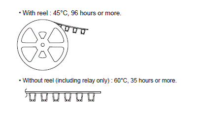
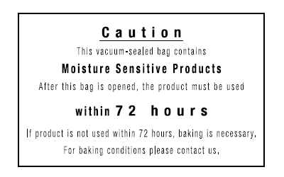
The following cautionary label is affixed to the anti-humidity pack.
  • *RE Relays only

Vibration, Impact and Pressure when Shipping

When shipping, if strong vibration, impact or heavy weight is applied to a device in which a relay is installed, functional damage may occur. Therefore, please package in a way, using shock absorbing material, etc., so that the allowable range for vibration and impact is not exceeded.

Return to top

Environmentally Sealed Type Relays

Sealed type relays are available. They are effective when problems arise during PC board mounting (e.g. automatic soldering and cleaning). They also, of course, feature excellent corrosion resistance. Note the cautions below regarding the features and use of environmentally sealed type relays to avoid problems when using them in applications.

Operating Environment

Plastic sealed type relays are not suited for use in environments that especially require air tightness. Although there is no problem if they are used at sea level, avoid atmospheric pressures beyond 96±10 kPa. Also avoid using them in an atmosphere containing flammable or explosive gases.

Cleaning

When cleaning a printed circuit board after soldering, we recommend using alcohol based cleaning fluids. Please avoid ultrasonic cleaning. The ultrasonic energy from this type of cleaning may cause coil line breakage and light sticking of contacts.

Return to top

Mounting Considerations

Top View and Bottom View

Relays used for PC boards, especially the flat type relays, have their top or bottom surface indicated in the terminal wiring diagrams.


Relay with terminals viewed from the bottom (terminals cannot be seen from the top)


Relay with terminals viewed from the top (all terminals can be seen from the top)
Note during PC board pattern design (NC relay)

Mounting Direction

Mounting direction is important for optimum relay characteristics.

Shock Resistance

It is ideal to mount the relay so that the movement of the contacts and movable parts is perpendicular to the direction of vibration or shock. Especially note that the vibration and shock resistance of Form B contacts while the coil is not excited is greatly affected by the mounting direction of the relay.

Contact Reliability

Mounting the relay so the surfaces of its contacts (fixed contacts or movable contacts) are vertical prevents dirt and dust as well as scattered contact material (produced due to large loads from which arcs are generated) and powdered metal from adhering to them.
Furthermore, it is not desirable to switch both a large load and a low level load with a single relay. The scattered contact material produced when switching the large load adheres to the contacts when switching the low level load and may cause contact failure. Therefore, avoid mounting the relay with its low level load contacts located below the large load contacts.

The installation direction is specified for some models. Please check with the product catalog and make sure to use the correct installation direction.

Adjacent Mounting

When many relays are mounted close together, abnormally high temperatures may result from the combined heat generated. Mount relays with sufficient spacing between them to prevent heat buildup.
This also applies when a large number of boards mounted with relays are installed as in a card rack. Be sure the ambient temperature of the relay does not exceed the value listed in the catalog.

Influence of Adjacent Mounting of Polarized Relays

When polarized relays are mounted close together, their characteristics change. Since the affect of adjacent mounting differs according to the type of relay, refer to the data for the particular type.

Panel Mounting

Do not remove the cover. It has a special function. (It will not come off under normal handling.)
When installing please use washers to prevent damage and deformation. Please keep the tightening torque to within 0.49 to 0.686 N·m (5 to 7 kgf·cm). Also, please use a spring washer to prevent it from coming loose.

Tab Terminals

As a guide, use a quick connect mounting pressure of 40 to 70 N {4 to 7 kgf} for relays with tab terminals.

Insulation distance

Be sure to maintain adequate insulating clearance between each terminal and ground

Return to top

Method of Mounting and Lead Wires Connection

Mounting Method

The direction of mounting is not specifically designated, but to the extent possible, the direction of contact movement should be such that vibration and shock will not be applied.

When a Terminal Socket is Used

  • After mounting terminal sockets, these sockets should be mounted making certain the mounting screws are not loose. DIN standard sockets are available for one-touch mounting on DIN rail of 35 mm width.

Precautions Regarding terminal socket and socket

Do not insert or remove relays while they are energized.

Do not attach other company relay.

Connection of Lead Wires

  • When making the connections, depending upon the size of load, the wire cross-section should be at least as large as the values shown in the table below.
    Also, please set the conductor cross-sectional area at the time of mounting the board based on the table .
Permissible current (A) Cross-section (mm2) AWG
2 0.2 24
3 0.3 22
5 0.5 20
7 0.8 18
10 1.3 16
15 2.1 14
20 3.3 12
30 5.3 10
40 8.4 8
55 13.3 6
70 21.2 4
85 26.7 3
95 33.6 2
110 42.4 1
120 53.5 1/0
  • When the terminal socket uses screw fastening connections, either pressure terminals or other means should be used to make secure fastening of the wire.
  • To prevent damage and deformity, please use a torque within the following range when tightening the push screw block of the terminal socket.
M4.5 screw : 1.47 to 1.666 N•m (15 to 17 kgf•cm)
M4 screw : 1.176 to 1.37 N•m (12 to 14 kgf•cm)
M3.5 screw : 0.784 to 0.98 N•m (8 to 10 kgf•cm)
M3 screw : 0.49 to 0.69 N•m (5 to 7 kgf•cm)

Return to top

10. Cautions for Use-Check List

Coil Drive Input

  • 1. Is the correct rated voltage applied?
  • 2. Is the applied coil voltage within the allowable continuous voltage limit?
  • 3.Is the ripple in the coil voltage within the allowable level?
  • 4.For voltage applied to a polarized coil, is polarity observed?
  • 5.When hot start is required, is the increase in coil resistance resulting from coil temperature rise taken into account in setting coil voltage?
  • 6.Is the coil voltage free from momentary drop caused by load current? (Pay special attention for self-holding relays.)
  • 7.Is supply voltage fluctuation taken into account when setting the rated coil voltage?
  • 8.The relay status may become unstable if the coil voltage (current) is gradually increased or decreased.
    Was the relay tested in a real circuit or with a real load?
  • 9.When driving with transistors, did you consider voltage drops?

Load (Relay Contacts)

  • 1.Is the load rated within the contact ratings?
  • 2.Does the load exceed the contacts' minimum switching capacity?
  • 3.Special attention is required for contact welding when the load is a lamp, motor, solenoid, or electromagnetic contractor. Was the relay tested with a real load?
  • 4.DC load may cause contact lock-up due to large contact transfer. Was the relay tested with a real load?
  • 5.For an inductive load, is a surge absorber used across the contacts?
  • 6.When an inductive load causes heavy arc discharge across the relay contacts, the contacts may be corroded by chemical reaction with nitrogen in the atmosphere. Was the relay tested with a real load?
  • 7.Platinum contacts may generate brown powder due to a catalyzer effect or vibration energy. Was the relay tested with a real load?
  • 8.Is the contact switching frequency below the specification?
  • 9.When there are more than two sets of contacts (2T) in a relay, metallic powder shed from one set of contacts may cause a contact failure on the other set (particularly for light loads). Was the relay tested in a real load?
  • 10.A delay capacitor used across relay contacts may cause contact welding. Was the relay tested with a real load?
  • 11.For an AC relay, a large contact bounce may cause contact welding. Was the relay tested in a real circuit or with a real load?
  • 12.A high voltage may be induced at transformer load. Was the relay tested with a real load?

Circuit Design

  • 1.Does circuit design take into account electrolytic corrosion of the coil?
  • 2.Are transistors and other circuit components protected rom counter electromotive force that develops across the relay coil?
  • 3.Is the circuit designed so the relay coil is left deenergized while the relay is inactive for long period of time?
  • 4.Is the relay operated within the ratings approved by the relevant international standard (if compliance is required)?
  • 5.Is the circuit protected from malfunction when the relay's activation and/or deactivation time varies considerably?
  • 6.Is the circuit protected from malfunctions that might result from relay contact bounce?
  • 7.Is the circuit protected from malfunction when a high-sensitivity self-holding relay, such as NR type, is to be used?
  • 8.When there are two or more sets of contacts (2T) in a relay, arc discharges from load switching may cause short circuits across the two or more sets of contacts. Is the circuit designed to suppress such arc discharges?
  • 9.Item 8 above also requires special attention when loads are supplied from separate power sources.
  • 10.Does the post-installation insulation distance comply with the requirement of the relevant international standard or the Electrical Appliance and Material Control Law?
  • 11.Is the circuit protected from malfunction when the relay is to be driven by transistors?
  • 12.When the SCR is used for on/off control, the relay activation tends to synchronize with the line frequency, resulting in an extremely shortened life. Was the relay tested in a real circuit or with a real load?
  • 13. Does the PC board design take into account use of on-board relay?
  • 14.RF signals may leak across relay's open contacts. Check for adequate contact isolation and use RF relays as needed.

Operating Environment

  • 1.Is the ambient temperature in the allowable operating temperature range?
  • 2.Is the humidity in the allowable humidity range?
  • 3.Is the operating atmosphere free from organic and sulfide gases?
  • 4.Is the operating atmosphere free from silicone gas? Depending on the load type, silicon gas may cause a black substance to from on the contacts, leading to contact failure.
  • 5.Is the operating atmosphere free from excessive airborne dust?
  • 6.Is the relay protected from oil and water splashes?
  • 7. Is the relay protected from vibration and impact which may cause poor contact with the socket?
  • 8. Is ambient vibration and impact below the level allowable for the relay?
  • 9.Is the relay free from mechanical resonance after it is installed in position?
  • 10.Is insulation coating applied to the relay along with the PC board? Depending on the load type, a black substance may form to cause contact failure.

Installation and Connection

  • 1.Is the relay protected from solder chips and flux when it is manually soldered?
  • 2.Are preparations for flux application and automatic soldering complete?
  • 3.Is the PC board cleaning process designed to minimize adverse affects to the relays?
  • 4.Are adequate separations provided between polarized or reed relays to prevent magnetic coupling?
  • 5. Are the relay terminals free from stress in the socket?
  • 6.Polarized relay's characteristics may be affected by strong external magnetic field. Are the relays installed away from such fields?
  • 7.If very long leads (several 10m more) are used to connect the load, the stray capacity existing across the leads may cause the inrush current. Was the relay tested with a real load?
  • 8.Unless otherwise specified, all relay terminals should be soldered at 250°C within 5 sec. or at 350°C within 3 sec.
  • 9.A badly warped PC board can cause stress to the relay terminals which may lead to degraded relay characteristics.
  • 10.Glass shot should not be used to clean the PC board of solder flux. This may cause relay malfunction due to glass powder becoming lodged in the relay's internal structure.
  • 11.Relays should always be used with their plastic shields installed, or degraded relay performance may result.
  • 12.Do not cut away any relay terminal as the stress may cause degraded relay performance.

Storage and Transport

  • 1.Is the relay subject to freezing or condensation (especially when shipping)?
  • 2.Is the temperature in the allowable temperature range?
  • 3.Is the humidity in the allowable humidity range?
  • 4.Is the storing atmosphere free from organic and sulfide gases?
  • 5.Is the storing atmosphere free from excessive airborne dust?
  • 6.Is the relay protected from oil and water splashes?
  • 7.Is the relay subject to the application of heavy weight?
  • 8.When shipping does vibration and impact exceed the allowable range?

Return to top


Catalog Download

RELATED INFORMATION Title Language File size Update
リレー使用上の注意事項
各種リレー共通 (パワー, 安全, シグナル, 高周波, 高容量, インターフェイスターミナル)
JP 608.7KB September 19, 2023
General Application Guidelines
Power Relays(Over 2A), Safty Relays, Signal Relays (2A or less), Microwave Devices, High-capacity DC Cutoff Relays, and Interface Terminal.
EN 404.4KB July 8, 2022
继电器使用上的注意事项 CN-Simplified 1.3MB November 21, 2023

Return to top

CONTACT US
BY EMAIL
Please click your area to select country or region


BY PHONE

Search Relays


Requests to customers (Automation Control Components & Industrial Device) [Excluding specific product]
Requests to customers (Automation Control Components & Industrial Device) [For specific product]
Requests to customers (FA Sensors & Components [Excluding motors])
Requests to customers (Dedicated to industrial motors)