 Business
> Industrial Devices
> Automation Controls Top
> Components & Devices
> Relays / Couplers
> PhotoIC Coupler
> 50 Mbps type
> Rating/Performance
50 Mbps type
|
Absolute maximum ratings (Ambient temperature: 25°C)
| Item | Symbol | APS1551S | Remarks | |
|---|---|---|---|---|
| Input | LED forward current | IF | 25 mA | |
| LED reverse voltage | VR | 5 V | ||
| Peak forward current | IFP | 1 A | f = 100 Hz, Duty factor = 0.1%, 1 shot | |
| Output | Supply voltage | VCC | 6 V | |
| Output voltage | V0 | 6 V | ||
| Output current | I0 | 10 mA | ||
| Power dissipation | Pout | 40 mW | ||
| I/O isolation voltage | Viso | 3,750 Vrms | ||
| Ambient temperature (Operating) | Topr | -40 to +105°C | (Avoid icing and condensation) | |
| Ambient temperature (Storage) | Tstg | -40 to +125°C | ||
| Junction temperature | Tj | 125°C | ||
Electrical characteristics (Unless otherwise specified, Ta = -40 to +105°C, VCC = 4.5 to 5.5 V)
| Item | Symbol | APS1551S | Condition | ||
|---|---|---|---|---|---|
| Input | Threshold input current | Maximum | IFHL | 5 mA | VCC = 5 V, VO < 0.6 V |
| LED dropout voltage | Minimum | VF | 1.45 V | IF = 10 mA, Ta = 25°C | |
| Typical | 1.6 V | ||||
| Maximum | 1.8 V | ||||
| Input capacitance | Typical | Ct | 20 pF | f = 1 MHz, VB = 0 V, Ta = 25°C | |
| Output | Low level supply current | Maximum | ICCL | 5 mA | IF = 10 mA |
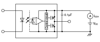
| High level supply current | Maximum | ICCH | 5 mA | IF = 0 mA | |
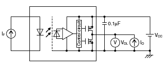
| Low level output voltage | Maximum | VOL | 0.6 V | IF = 10 mA, IO = 4 mA, Vcc = 5 V | |
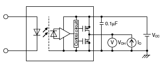
| High level output voltage | Minimum | VOH | 4.4 V | IF = 0 mA, IO = -4 mA, Vcc = 5 V | |
| Item | Symbol | APS1551S | Condition | ||
|---|---|---|---|---|---|
| Transfer characteristics |
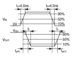
Propagation delay time (H ➝ L) |
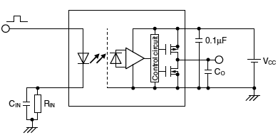
Maximum | tpHL | 30 ns | VIN = 0 ➝ 5 V, RIN = 300 Ω CIN = 22 pF, CO = 15 pF |
| Propagation delay time (L ➝ H) |
Maximum | tpLH | 30 ns | VIN = 5 ➝ 0 V,, RIN = 300 Ω CIN = 22 pF, CO = 15 pF |
|
| Propagation delay skew | Maximum | tpsk | 16 ns | - | |
| Pulse width distortion | Maximum | |tpHL-tpLH| | 10 ns | VIN = 5 V/25 MHz, RIN = 300 Ω CIN = 22 pF, CO = 15 pF |
|
| Output fall time | Typical | tf | 5 ns | VIN = 0 ➝ 5 V, RIN = 300 Ω CIN = 22 pF, CO = 15 pF |
|
| Output rise time | Typical | tr | 4 ns | VIN = 5 ➝ 0 V, RIN = 300 Ω CIN = 22 pF, CO = 15 pF |
|
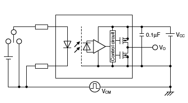
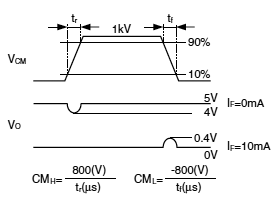
| Common mode transient immunity at low level output |
Minimum | CML | 15 kV/μs | VCM = 1000 Vp-p', IF = 10 mA, VCC = 5 V, VO (MAX) = 0.4 V, Ta = 25°C |
|
| Common mode transient immunity at high level output |
Minimum | CMH | 15 kV/μs | VCM = 1000 Vp-p', IF = 0 mA, VCC = 5 V, VO (MIN) = 4 V, Ta = 25°C |
|
| I/O capacitance | Typical | Ciso | 0.5 pF | f = 1 MHz, VB = 0 V, Ta = 25°C | |
| Initial I/O isolation resistance | Minimum | Riso | 1000 MΩ | 500 V DC, RH ≦ 60%, Ta = 25°C | |
|
|
||||
|
|
|
||||||
|
||||||
Recommended operating conditions
Please use under recommended operating conditions to obtain expected characteristics.
| Item | Symbol | Min. | Typ. | Max. | Unit |
|---|---|---|---|---|---|
| LED forward current | IF | 10 | — | 16 | mA |
| Supply voltage | VCC | 4.5 | 5 | 5.5 | V |
| LED off voltage | VF(OFF) | 0 | — | 0.8 | V |
|
Related Information
BY EMAIL
- U.S.A.
- +1-800-344-2112
- Europe
- +49-89-45354-1000
- China
- +86-10-59255988
- Singapore
- +65-6299-9181
Requests to customers (Automation Control Components & Industrial Device) [Excluding specific product]
Requests to customers (Automation Control Components & Industrial Device) [For specific product]
Requests to customers (FA Sensors & Components [Excluding motors])
Requests to customers (Dedicated to industrial motors)
- COMPONENTS & DEVICES
- FA SENSORS & COMPONENTS
- Fiber Sensors
- Photoelectric Sensors / Laser Sensors
- Micro Photoelectric Sensors
- Light Curtains / Safety Components
- Area Sensors
- Inductive Proximity Sensors
- Particular Use Sensors
- Sensor Options
- Wire-Saving Systems
- Programmable Controllers / Interface Terminal
- Human Machine Interface
- Pressure Sensors / Flow Sensors
- Measurement Sensors
- Static Control Devices
- Laser Markers / 2D Code Readers
- Machine Vision System
- Energy Management Solutions
- Timers / Counters / FA Components
- MOTORS


