
 Business
> Industrial Devices
> Automation Controls Top
> Components & Devices
> Relays / Couplers
> Power Relays (Over 2A)
> Power Relays (Over 2A) Lineup
> HE Relays
> Dimensions
Business
> Industrial Devices
> Automation Controls Top
> Components & Devices
> Relays / Couplers
> Power Relays (Over 2A)
> Power Relays (Over 2A) Lineup
> HE Relays
> Dimensions
HE Relays
-
Lineup
-
 DE Relays
Compliant with European safety standards, 1 Form A/2 Form A/1 Form A 1 Form B 10 A/8 A Polarized power relays
DE Relays
Compliant with European safety standards, 1 Form A/2 Form A/1 Form A 1 Form B 10 A/8 A Polarized power relays
-
 DJ Relays
High insulation, 1-pole/2-pole 16 A, Polarized power relays
DJ Relays
High insulation, 1-pole/2-pole 16 A, Polarized power relays
-
 DJ-H Relays
Suitable for lighting and motor load, 1 Form A 50 A, Latching relays
DJ-H Relays
Suitable for lighting and motor load, 1 Form A 50 A, Latching relays
-
 DK Relays
1 Form A 10 A, 1 Form A 1 Form B/2 Form A 8 A, Small polarized power relays
DK Relays
1 Form A 10 A, 1 Form A 1 Form B/2 Form A 8 A, Small polarized power relays
-
 DS Power Relays
1 Form A 8 A (AC) / 5 A (DC) , 1 Form A 1 Form B/2 Form A 5 A (AC/DC) , Small polarized power relays
DS Power Relays
1 Form A 8 A (AC) / 5 A (DC) , 1 Form A 1 Form B/2 Form A 5 A (AC/DC) , Small polarized power relays
-
 DW Relays
1 Form A 8 A/16 A, Small, Polarized power relays (latching type)
DW Relays
1 Form A 8 A/16 A, Small, Polarized power relays (latching type)
-
 DY Relays
1 Form A 10 A, 1 Form A 1 Form B 8 A, Small polarized power relays
DY Relays
1 Form A 10 A, 1 Form A 1 Form B 8 A, Small polarized power relays
-
 DZ-S Relays
IEC62055-31 UC3 compliant, 1 Form A 90 A, Power latching relays
DZ-S Relays
IEC62055-31 UC3 compliant, 1 Form A 90 A, Power latching relays
-
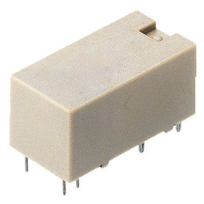
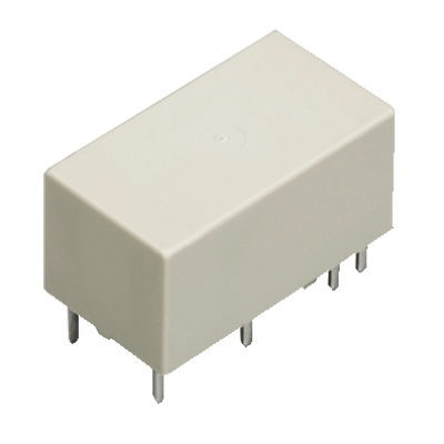
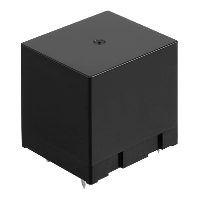
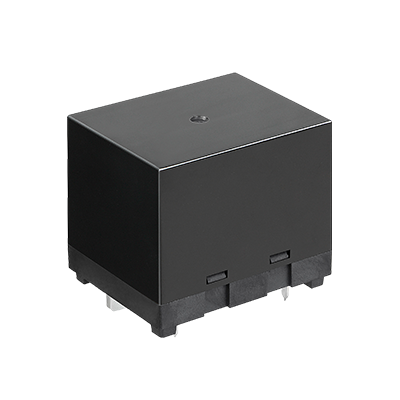
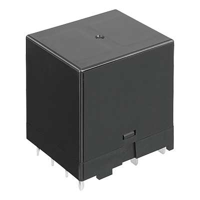
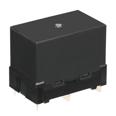
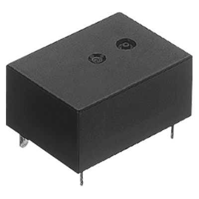
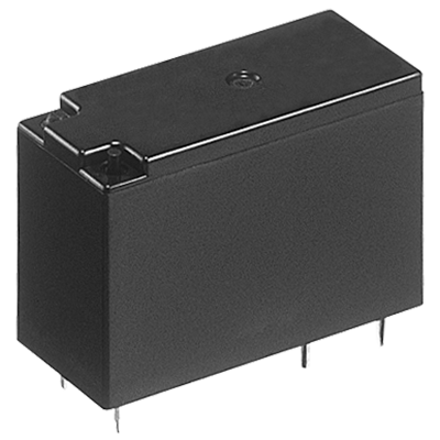
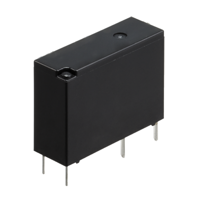
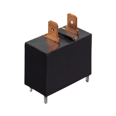
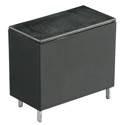
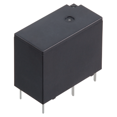
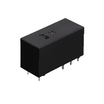
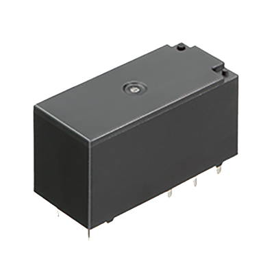
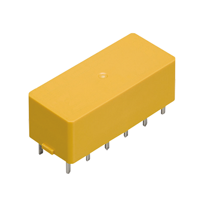
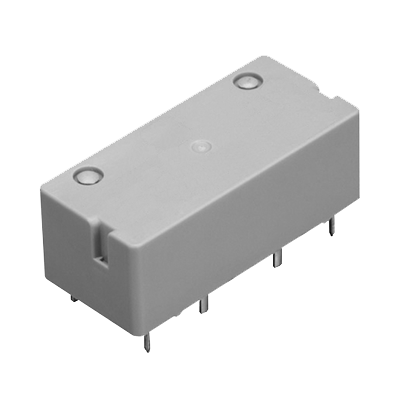
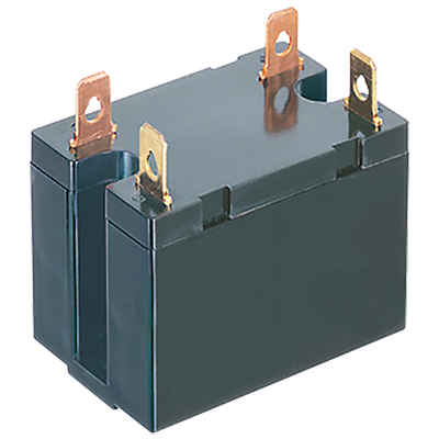 HE Relays
TV-10/TV-15 rated, 1 Form A 30 A, 2 Form A 25 A, Power relays
HE Relays
TV-10/TV-15 rated, 1 Form A 30 A, 2 Form A 25 A, Power relays
-
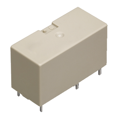
 HE Relays PV Type
Compact size, 1 Form A 35 A/48 A/90 A Power relays for solar inverter
HE Relays PV Type
Compact size, 1 Form A 35 A/48 A/90 A Power relays for solar inverter
-
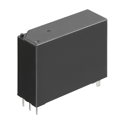
 HE-N Relays
High capacity 120 A 490 V AC 1 Form A power relay
HE-N Relays
High capacity 120 A 490 V AC 1 Form A power relay
-
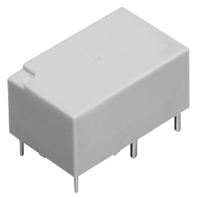
 HE-S Relays
Compact size 2a and 2a1b 40 A power relays for energy management and industrial equipment
HE-S Relays
Compact size 2a and 2a1b 40 A power relays for energy management and industrial equipment
-
 HE-R Relays
Compact size 2 Form A and 2 Form A 1Form B 80 A/4 Form A and 4 Form A and 1 Form B 40 A power relays
HE-R Relays
Compact size 2 Form A and 2 Form A 1Form B 80 A/4 Form A and 4 Form A and 1 Form B 40 A power relays
-
 JV-N Relays
1 Form A 16 A, low profile: 10.9 mm power relays for heater control
JV-N Relays
1 Form A 16 A, low profile: 10.9 mm power relays for heater control
-
 JW Relays
1 Form A/1 Form C/2 Form A/2 Form C, 5 A/10 A, Power relays
JW Relays
1 Form A/1 Form C/2 Form A/2 Form C, 5 A/10 A, Power relays
-
 LD-P Relays
Compliant with IEC/EN60335-1/ EN60079-15 (VDE approved) 1 Form A 5 A Slim power relays
LD-P Relays
Compliant with IEC/EN60335-1/ EN60079-15 (VDE approved) 1 Form A 5 A Slim power relays
-
 LF Relays
Ideal for compressor and inverter loads, 1 Form A 20 A, Power relays
LF Relays
Ideal for compressor and inverter loads, 1 Form A 20 A, Power relays
-
 LF-G Relays
Load for solar inverter, Compact size, 1 Form A 22 A/33 A, Power relays
LF-G Relays
Load for solar inverter, Compact size, 1 Form A 22 A/33 A, Power relays
-
 LQ Relays
Compliant with IEC/EN60335-1*1*2 /EN60079-15*3 (VDE approved) 1 Form A/1 Form C 10A small power relays
LQ Relays
Compliant with IEC/EN60335-1*1*2 /EN60079-15*3 (VDE approved) 1 Form A/1 Form C 10A small power relays
-
 LZ Relays
Low profile: 15.7 mm, 1 Form A/1 Form C 16 A, Power relay
LZ Relays
Low profile: 15.7 mm, 1 Form A/1 Form C 16 A, Power relay
-
 LZ-N Relays
EN60335-1 GWT compliant, 15.7 mm Low profile, 1 Form A/1 Form C 16 A, Power relays
LZ-N Relays
EN60335-1 GWT compliant, 15.7 mm Low profile, 1 Form A/1 Form C 16 A, Power relays
-
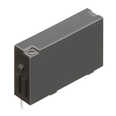
 NC Relays
Transistor drive, 2 Form C/4 Form C, 5 A Slim power relays
NC Relays
Transistor drive, 2 Form C/4 Form C, 5 A Slim power relays
-
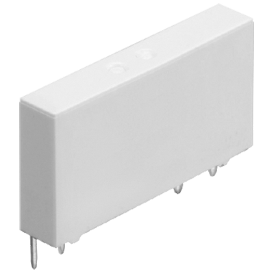
 PA-N Relays
Complies with IEC61010 reinforced insulation, For PLC/Interface, 1 Form A 5 A, Slim power relay
PA-N Relays
Complies with IEC61010 reinforced insulation, For PLC/Interface, 1 Form A 5 A, Slim power relay
-
 PF Relays
Compliant with European standards, 1 Form A/1 Form C 6 A, Slim power relays
PF Relays
Compliant with European standards, 1 Form A/1 Form C 6 A, Slim power relays
-
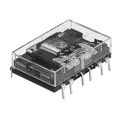
 S Relays
2 Form A 2 Form B/3 Form A 1 Form B/4 Form A /4 A Polarized power relays
S Relays
2 Form A 2 Form B/3 Form A 1 Form B/4 Form A /4 A Polarized power relays
-
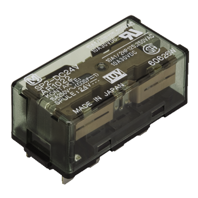 SP Relays
2 Form C 15 A, 4 Form C 10 A, Polarized power relays
SP Relays
2 Form C 15 A, 4 Form C 10 A, Polarized power relays
-
 ST Relays
1 Form A 1 Form B/2 Form A, 8 A, Polarized power relays
ST Relays
1 Form A 1 Form B/2 Form A, 8 A, Polarized power relays
-
- CAD data Catalogs/Datasheets
- FAQ
1.PC board terminal
1 Form A
|
|
|

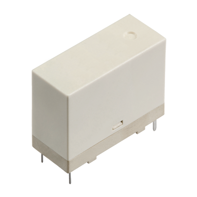
2.Plug-in terminal
1 Form A
|
|
|
2 Form A
|
|
|
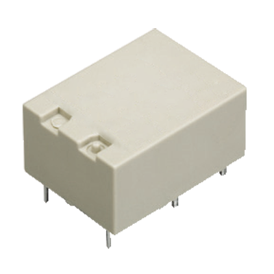
3.TM type
1 Form A
|
|
|
2 Form A
|
|
|
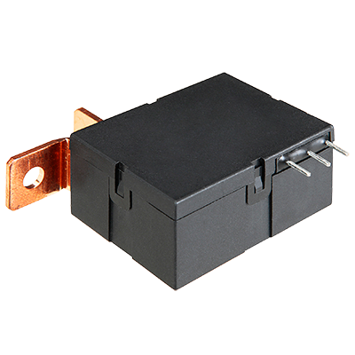
4.Screw terminal
1 Form A
|
|
|
2 Form A
|
|
|
5.Terminal Sockets
|
|
|
|
BY EMAIL
- U.S.A.
- +1-800-344-2112
- Europe
- +49-89-45354-1000
- China
- +86-10-59255988
- Singapore
- +65-6299-9181


Requests to customers (Automation Control Components & Industrial Device) [Excluding specific product]
Requests to customers (Automation Control Components & Industrial Device) [For specific product]
Requests to customers (FA Sensors & Components [Excluding motors])
Requests to customers (Dedicated to industrial motors)
- COMPONENTS & DEVICES
- FA SENSORS & COMPONENTS
- Fiber Sensors
- Photoelectric Sensors / Laser Sensors
- Micro Photoelectric Sensors
- Light Curtains / Safety Components
- Area Sensors
- Inductive Proximity Sensors
- Particular Use Sensors
- Sensor Options
- Wire-Saving Systems
- Programmable Controllers / Interface Terminal
- Human Machine Interface
- Pressure Sensors / Flow Sensors
- Measurement Sensors
- Static Control Devices
- Laser Markers / 2D Code Readers
- Machine Vision System
- Energy Management Solutions
- Timers / Counters / FA Components
- MOTORS
![]()