
 Business
> Industrial Devices
> Automation Controls Top
> Components & Devices
> Relays / Couplers
> Solid State Relays
> SSR Principle of Operation
Business
> Industrial Devices
> Automation Controls Top
> Components & Devices
> Relays / Couplers
> Solid State Relays
> SSR Principle of Operation
SSR Principle of Operation
SSR Switching Characteristics
1.SSR for AC Loads
1.Zero-crossing SSR
The zero-crossing SSR uses a phototriac coupler to isolate the input from the output (see the circuit configuration on the previous page). When the input signal is activated, the internal zero-crossing detector circuit triggers the triac to turn on as the AC load voltage crosses zero.
The load current is maintained by the triac’s latching effect after the input signal is deactivated, until the triac is turned off when the load voltage crosses zero. The following describes voltage and current wave forms for different types of loads:
●Resistive loads
Since resistive loads cause no phase shift between the voltage and current, the triac turns on when the AC load voltage crosses zero after the input signal is activated. The SSR turns off when the AC load voltage crosses zero and the load current is turned off after the input signal is subsequently deactivated.
●Inductive loads
The SSR turns on when the load voltage crosses zero after the input signal is activated. It turns off when the load current subsequently crosses zero after the input signal is deactivated. A phase difference between the voltage and current may supply a transient spike to the SSR when it is turned off. While the snubber circuit absorbs this spike, an excessively large spike may result in a dv/dt error in the SSR’s internal triac.
2.Random type SSR
Random type SSR uses a phototriac coupler to isolate the input from the output. When the input signal is activated, the output immediately turns on, since there is no zero-crossing detector circuit. The load current is maintained by the triac’s latching effect after the input signal is deactivated, until the AC load voltage crosses zero.
●Resistive loads
2.SSR for DC Loads
The SSR for DC loads uses a MOS-FET driver to isolate the input from the output.
The output immediately responds to the input, since the MOS-FET driver directly turns the output MOS-FET ON or OFF.
Catalog Download
|
|
Title | Language | File size | Update |
|---|---|---|---|---|
| SSR動作原理の説明 ソリッドステートリレー |
JP | 120.9KB | April 1, 2022 | |
| SSR Principle of Operation Solid State Relays |
EN | 49.3KB | April 1, 2022 | |
| SSD工作原理的说明 | CN-Simplified | 345.6KB | August 22, 2019 |
BY EMAIL
- U.S.A.
- +1-800-344-2112
- Europe
- +49-89-45354-1000
- China
- +86-10-59255988
- Singapore
- +65-6299-9181


Solid State Relays
-
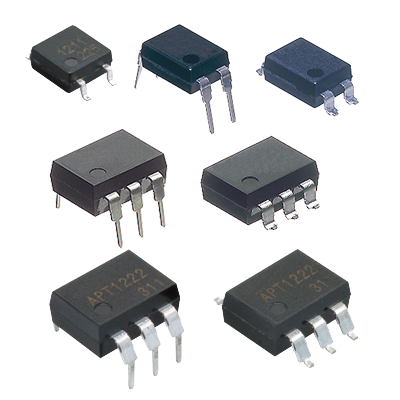
Phototriac Coupler Phototriac coupler for the industrial machinery and consumer electronics -
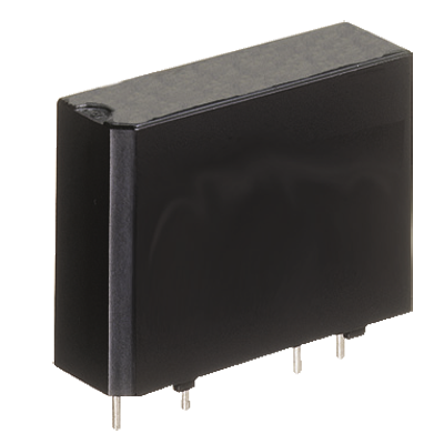
AQ1 Solid State Relay High capacity up to 3 A/10 A PC board terminal type -
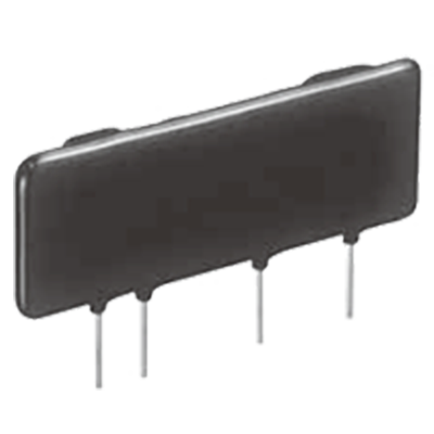
AQ8 Solid State Relay SIL type with 9 mm thickness, 3,000 V AC high dielectric voltage, controls up to 2 A/3 A -

AQ-A (AC output type) Solid State Relay Load current up to Max. 40 A in the series, Small Screw Terminal SSR -
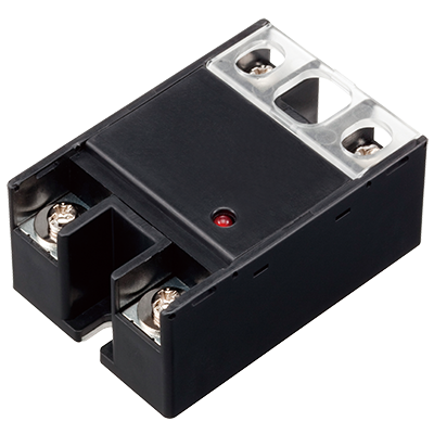
AQ-A (DC output type) Solid State Relay Small Screw Terminal SSR Ideal for DC Control -
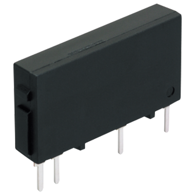
AQ-G Solid State Relay Slim type SSR for 1 A and 2 A control -
AQ-H Solid State Relay Compact DIP type SSR Ideal for AC load control -
AQ-J Solid State Relay Small tab terminal SSR, Slim heat sink combined type also available
Requests to customers (Automation Control Components & Industrial Device) [Excluding specific product]
Requests to customers (Automation Control Components & Industrial Device) [For specific product]
Requests to customers (FA Sensors & Components [Excluding motors])
Requests to customers (Dedicated to industrial motors)
- COMPONENTS & DEVICES
- FA SENSORS & COMPONENTS
- Fiber Sensors
- Photoelectric Sensors / Laser Sensors
- Micro Photoelectric Sensors
- Light Curtains / Safety Components
- Area Sensors
- Inductive Proximity Sensors
- Particular Use Sensors
- Sensor Options
- Wire-Saving Systems
- Programmable Controllers / Interface Terminal
- Human Machine Interface
- Pressure Sensors / Flow Sensors
- Measurement Sensors
- Static Control Devices
- Laser Markers / 2D Code Readers
- Machine Vision System
- Energy Management Solutions
- Timers / Counters / FA Components
- MOTORS
![]()