Here is PDF of this page.
1. Protective Construction
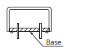
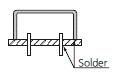
Dust cover type
To protect from dust, these types are covered, for example, with a plastic case.
We recommend hand soldering, because these relays are not constructed to prevent flux and cleaning fluid from entering during automatic soldering.
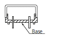
Flux-resistant type
The relay is constructed so that flux will not enter inside the relay during automatic soldering. However, cleaning is not possible.
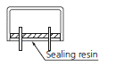
Sealed type
Construction is designed to prevent seeping of flux when soldering and cleaning fluid when cleaning. Harmful substances on the contacts are removed by gas purging before sealing with.
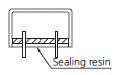
Sealed capsule type
This type is hermetically sealed with ceramic and metal plating. No harmful gas or humidity will ever reach the contacts. This type cannot be washed.
Construction and characteristics
* Since the plastic material is porous, please avoid atmospheric exposure to silicon.
2. Operational Function
Single side stable type
Relay which turns on when the coil is energized and turns off when de-energized.
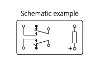
1 coil latching type
Relay with latching construction that can maintain the on or off state with a pulse input.
With one coil, the relay is set or reset by applying signals of opposite polarities.
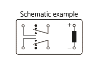
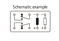
2 coil latching type
Relay with latching construction composed of 2 coils: set coil and reset coil. The relay is set or reset by alternately applying pulse signals of the same polarity.
Operation indication
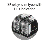
Indicates the set and reset states (electrically or mechanically) for easy maintenance. Also available are an LED version (SF relays slim type with LED).
3. Terminal Configuration
Mounting method
Note) Sockets are available for certain PC board relays. (S relay, ST relay, etc.)
4. Coil Rating
Rated coil voltage
A single value (or narrow range) of source voltage intended by design to be applied to the coil or input.
Operate voltage (Set voltage)
As the voltage on an unoperated relay is increased, the value at or below which all contacts must function (transfer).
For latching relays, the voltage at the time of operation from the reset state to the set state is called the set voltage.
Release voltage (Reset voltage)
As the voltage on an operated relay is decreased, the value at or above which all contacts must revert to their unoperated position.
The operate voltage (set voltage) and the release voltage (reset voltage) are normally specified at a temperature of 20°C, but some relays are 25°C, so check the values in the catalog.
Rated operating current
The value of current flow in the coil when rated voltage is impressed on the coil.
Coil resistance
This is the DC resistance of the coil in DC type relays for the temperature conditions listed in the catalog. (Note that for certain types of relays, the DC resistance may be for temperatures other than the standard 20°C)
Rated operating power
The value of power used by the coil at rated voltage. For DC coils expressed in watts; AC expressed as volt amperes.
Rated operating power (W or VA) = Rated voltage x Rated current.
Max. allowable voltage
This is the maximum voltage tolerance that can be applied to the operating coil. However, it is not a continuous tolerance. It depends on the ambient temperature, so please check the catalog value according to the type.
Coil Designation
A black coil represents the energized state. For latching relays, schematic diagrams generally show the coil in its reset state.
Therefore, the coil symbol is also shown for the reset coil in its reset state.
5. Contact Rating
Contact arrangement
Denotes the contact mechanism and number of contacts in the contact circuit.
Contact symbols
- Form A contacts are also called N.O. contacts or make contacts.
- Form B contacts are also called N.C. contacts or break contacts.
- Form C contacts are also called changeover contacts or transfer contacts.
MBB contacts
Abbreviation for make-before-break contacts. Contact mechanism where Form A contacts (normally open contacts) close before Form B contacts open (normally closed contacts).
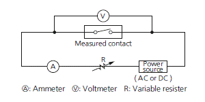
Contact resistance
This value is the combined resistance of the resistance when the contacts are touching each other, the resistance of the terminals and contact spring. The contact resistance is measured using the voltage-drop method as shown below. The measuring currents are designated.
Test Currents
In general, for relays with a contact rating of 1 A or more, measure using the voltage-drop method at 6 V DC 1 A.
Contact material
Material used for relay contacts.
Contact rating
It is a reference value that determines the performance of the relay switching section and is expressed by the combination of the contact voltage and the contact current.
Max. switching power
The upper limit of power which can be switched by the contacts. Care should be taken not to exceed this value.
Max. switching voltage
The maximum open circuit voltage which can safely be switched by the contacts.
AC and DC voltage maximums will differ in most cases.
Max. switching current
The maximum current which can safely be switched by the contacts. AC and DC current maximums may differ.
Contact carrying current
This is a current that can be continuously energized to the opening/closing part without exceeding the temperature rise limit of the relay contact terminal and other parts while the contact is closed.
Min. switching load
A value that serves as a guide for the lower limit of openable/closable at a small load level. This value depends on the frequency of opening and closing, environmental conditions, required contact resistance change, and absolute value. Use AgPd contact relays if you require analog microload control. Contact our sales representative before use.
6. Electrical Performance
Insulation resistance
The resistance value between all mutually isolated conducting sections of the relay, i.e. between coil and contacts, across open contacts and between coil or contacts to any core or frame at ground potential. This value is usually expressed as "initial insulation resistance" and may decrease with time, due to material degradation and the accumulation of contaminants.
Dielectric strength
The maximum voltage which can be tolerated by the relay without damage for a specified period of time, usually measured at the same points as insulation resistance. Usually the stated value is in VAC (RMS) for one minute duration.
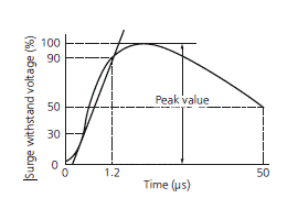
Surge withstand voltage
The ability of the device to withstand an abnormal externally produced power surge, as in a lightning strike, or other phenomenon. An impulse test waveform is usually specified, indicating rise time, peak value and fall time.
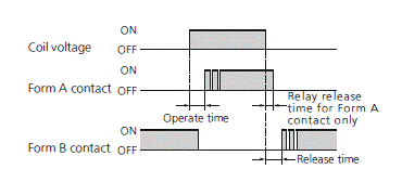
Operate Time (Set Time)
The elapsed time from the initial application of power to the coil, until the closure of the Form A (normally open) contacts. (With multiple pole devices the time until the last contact closes.) This time does not include any bounce time. In the case of a latching relay, the time from the application of the rated voltage to the set coil in the reset state to the contact of the Form A contact is called the set time.
Release Time (Reset Time)
The elapsed time from the initial removal of coil power until the reclosure of the Form B (normally closed) contacts (last contact with multi-pole). This time does not include any bounce time.
In the case of a latching relay, this refers to the time from the application of the rated voltage to the reset coil in the set state until the contact Form B comes into contact.
In the case of relay with only Form A contact (1 Form A, 2 Form A), the time until the contact is opened.
Contact bounce (Time)
Generally expressed in time (ms), this refers to the intermittent switching phenomenon of the contacts which occurs due to the collision between the movable metal parts or contacts, when the relay is operated or released.
7. Mechanical Performance
Shock resistance
Shock resistance is divided into Functional and Destructive, and each of them has the following meaning.
1) Functional
The shock which can be tolerated by the relay during service, without causing the closed contacts to open for more than the specified time or without causing the open contacts to close for more than the specified time. (usually 10 μs)
2) Destructive
The shock which can be withstood by the relay during shipping or installation without it suffering damage, and without causing a change in its operating characteristics. Usually expressed in "G" s. However, test was performed a total of 18 times, six times each in three-axis directions.
Vibration Resistance
Vibration resistance is divided into Functional and Destructive, and each of them has the following meaning.
1) Functional
The vibration which can be tolerated by the relay during service, without causing the closed contacts to open for more than the specified time or without causing the open contacts to close for more than the specified time. (usually 10 μs)
2) Destructive
The vibration which can be withstood by the relay during shipping, installation or use without it suffering damage, and without causing a change in its operating characteristics. Expressed as an acceleration in G's or displacement, and frequency range. However, test was performed a total of six hours, two hours each in three-axis directions.
8. Life
Mechanical Life
The minimum number of times the relay can be operated under nominal conditions (coil voltage, temperature, humidity, etc.) with no load on the contacts.
Electrical Life
The minimum number of times the relay can be operated under nominal conditions with a specific load being switched by the contacts.
9. Reference Data
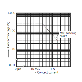
Max. switching capacity
This is listed in the data column for each type of relay as the maximum value of the contact capacity and is an interrelationship of the maximum switching power, maximum switching voltage, and maximum switching current.
The switching current and switching voltage can be obtained from this graph.
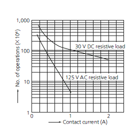
Switching life curve
This is listed in the data column for each type of relay. The life (number of operations) can be estimated from the switching voltage and switching current.
For example, for a DS relay operating at:
Switching voltage = 125 V AC
Switching current = 0.6 A
The life expectancy is 300 x 103 operations.
However, this value is for a resistive load. Be sure to carefully check the actual load before use.
10. High Frequency Characteristics
V.S.W.R. (Voltage Standing Wave Ratio)
High frequency resonance is generated from the interference between the input signal and reflected (wave) signal. V.S.W.R. refers to the ratio of the maximum value to minimum value of the waveform. The V.S.W.R. is 1 when there is no reflected wave. It usually becomes greater than 1.
Insertion Loss
At the high frequency region, signal disturbance occurs from self-induction, resistance, and dielectric loss as well as from reflection due to impedance mismatching in circuits. Loss due to any of these types of disturbances is called insertion loss. Therefore, this refers to the magnitude of loss of the input signal. The smaller the magnitude, the better the relay.
Isolation
High frequency signals leak through the stray capacitance across contacts even if the contacts are separated. This leak is called isolation. The symbol dB (decibel) is used to express the magnitude of the leak signal. This is expressed as the logarithm of the magnitude ratio of the signal generated by the leak with respect to the input signal. The larger the magnitude, the better the isolation.
Related Information