
 Business
> Industrial Devices
> Automation Controls Top
> Components & Devices
> Switches
> Non Seal Type Switches
> AEQ (EQ) Switches
> Rating/Performance
Business
> Industrial Devices
> Automation Controls Top
> Components & Devices
> Switches
> Non Seal Type Switches
> AEQ (EQ) Switches
> Rating/Performance
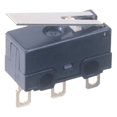
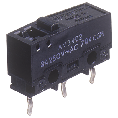
AEQ (EQ) Switches
-
Lineup
-
 AV6 (CS) Switches
Subminiature Size Connector Integrated Type
AV6 (CS) Switches
Subminiature Size Connector Integrated Type
-
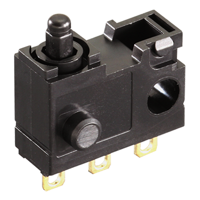 AEQ (EQ) Switches
Sliding contact construction Switches for Low-level Loads
AEQ (EQ) Switches
Sliding contact construction Switches for Low-level Loads
-
 AH1 (FJ) Switches
Ultra-miniature Size Switches High Precision
AH1 (FJ) Switches
Ultra-miniature Size Switches High Precision
-
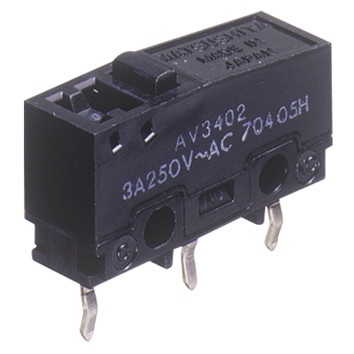
 AV3/AVM3 (FS) Switches
Subminiature Size Switches with Excellent Operating Position Accuracy
AV3/AVM3 (FS) Switches
Subminiature Size Switches with Excellent Operating Position Accuracy
-
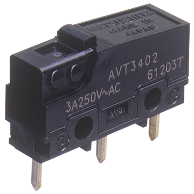 AVT3/AVL3 (FS-T) Switches
Subminiature Size Switches with Excellent Operating Position Accuracy
AVT3/AVL3 (FS-T) Switches
Subminiature Size Switches with Excellent Operating Position Accuracy
-
 AV3 (FS) Switches Contact gap 1 mm Type
Subminiature Size Door Inter-lock Switches
AV3 (FS) Switches Contact gap 1 mm Type
Subminiature Size Door Inter-lock Switches
-
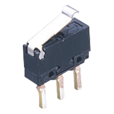 AV4 (FU) Switches
Ultra-miniature Size, Light-weight Snap action Switches
AV4 (FU) Switches
Ultra-miniature Size, Light-weight Snap action Switches
-
- CAD data Catalogs/Datasheets
- FAQ
|
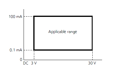
Contact rating
100 μA 3 V DC to 100 mA 30 V DC.
[Min. switching capacity (Reference value*) 10 μA 1 V DC]
| * | This value is a rough indication of the lowest possible low level load at which switching is possible. This value can change due to the switching frequency, environmental conditions, and desired reliability level, therefore it is recommended to check this with the actual load. |
|---|
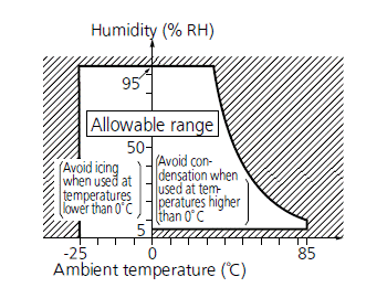
Operation environment and conditions
| Item | Specifications |
|---|---|
| Ambient and storage temperature | –25°C to +85°C (no freezing and condensing) |
| Allowable operating speed | 30 to 500 mm/sec. |
| Max. operating cycle rate | 120 cpm |
| *1 | When switching at low and high speeds or under vibration, or in high-temperature, high-humidity environments, life and performance may be reduced significantly depending on the load capacity. Please consult us. |
|---|---|
| *2 |
|
Electrical characteristics
| Dielectric strength (Initial) | Between non-continuous terminals: 600 Vrms for 1 min, Between each terminal and other exposed metal parts: 1,500 Vrms for 1 min, Between each terminal and ground: 1,500 Vrms for 1 min (at detection current of 1 mA) |
|---|---|
| Insulation resistance (Initial) | Min. 100 MΩ (at 500 V DC insulation resistance meter, Locations measured same as breakdown voltage.) |
| Contact resistance (Initial) | Max. 1 Ω (by voltage drop 0.1 A, 6 to 8 V DC) |
Characteristics
| Item | Specifications | ||
|---|---|---|---|
| Electrical switching life |
3 V DC 0.1 mA (resistive load) |
Min. 2 x 10⁵ | Switching frequency: 20 times/min. Conduction ratio: 1:1 Pushbutton operation speed: 100 mm/s Pushbutton switching position: free position (FP) to total travel position (TTP) |
| 30 V DC 100 mA (resistive load) |
Min. 105 | ||
| Vibration resistance (malfunction vibration resistance) |
Single amplitude: 0.75 mm Amplitude of vibration: 10 to 55 Hz (4 minutes cycle) Direction and time: 2 hours each in X, Y and Z directions |
||
| Shock resistance (malfunction shock resistance) |
Shock value: 294 m/s2 Direction and time: 3 times each in X, Y and Z directions |
||
| Vibration resistance endurance | Frequency of vibration: 33.3 Hz, Acceleration: 43.1 m/s2 Direction and time: 8 hours each in X, Y and Z directions |
||
| Terminal strength | Min. 6 N (to each direction, applied power at 1 minute) *Terminal deformation possible. |
||
| Salt spray resistance | Density of salt water: 5 % Temperature: 35°C each 100 hours At free position (FP) and total travel position (TTP) |
||
| Heat and cold resistance | -45 to -40°C 48 hours 85 to 90°C 48 hours |
||
| Humidity resistance | 40°C 95% RH 96 hours | ||
| Unit weight | Approx. 0.8 g | ||
| Protection grade | IP40 | ||
| * | As long as there are no particular designations, the following conditions apply to the test environment. ・Ambient temperature: 5 to 35°C ・Relative humidity: 25 to 85% RH ・Air pressure: 86 to 106 kPa |
|---|
Operating characteristics
| Characteristics | Pin plunger | Leaf lever | Simulated leaf lever | |
|---|---|---|---|---|
| Operating Force (OF) Max. *2 | 1.2 N | 1.7 N | 1.5 N | |
| Total travel Force (TF) Max. (reference value) | (1.8 N) | (3.1 N) | (2.8 N) | |
| Free Position (FP) Max. | From mounting boss and hole center line |
9.2 mm | 11.5 mm | 14.4 mm |
| From standoff | 13.4 mm | 15.7 mm | 18.6 mm | |
| Operating Position on N.C. side (OP) N.C.*3, 5 |
From mounting boss and hole center line |
8.7±0.3 mm | 9.8±0.5 mm | 12.5±0.5 mm |
| From standoff | 12.9±0.3 mm | 14.0±0.3 mm | 16.7±0.3 mm | |
| Operating Position on N.O. side (OP) N.O.*4, 5 |
From mounting boss and hole center line |
8.4±0.3 mm | 9.3±0.5 mm | 12.0±0.5 mm |
| From standoff | 12.6±0.3 mm | 13.5±0.3 mm | 16.2±0.3 mm | |
| Release Position on N.C. side (RP) N.C. *6 |
From mounting boss and hole center line |
8.8±0.3 mm | 10.1±0.5 mm | 12.9±0.5 mm |
| From standoff | 13.0±0.3 mm | 14.3±0.3 mm | 17.1±0.3 mm | |
| Release Position on N.O. side (RP) N.O. *7 |
From mounting boss and hole center line |
8.5±0.3 mm | 9.6±0.5 mm | 12.4±0.5 mm |
| From standoff | 12.7±0.3 mm | 13.8±0.5 mm | 16.6±0.5 mm | |
| Over travel on N.C. side (OT) N.C. Min. | 2.5 mm | 3.1 mm | 3.3 mm | |
| Over travel on N.O. side (OT) N.O. Min. | 2.2 mm | 2.6 mm | 2.8 mm | |
| Total Travel Position (TTP) (reference value) |
From mounting boss and hole center line |
(5.9 mm) | (6.2 mm) | (8.7 mm) |
| From standoff | (10.1 mm) | (10.4 mm) | (12.9 mm) | |
| *1 | The above indicates the characteristics when operating the pushbutton from the vertical direction. |
|---|---|
| *2 | Indicates operation load for N.O. contact to achieve ON status. |
| *3 | Indicates position for N.C. contact to achieve OFF status. |
| *4 | Indicates position for N.O. contact to achieve ON status. |
| *5 | Although there is some overlap in the range of the operating position (OP) on the N.C. and N.O. sides due to the tolerance, in actuality there is always an intermediate OFF range (the N.C. and N.O. sides will never ON at the same time.) |
| *6 | Indicates position for N.C. contact to achieve ON status. |
| *7 | Indicates position for N.O. contact to achieve OFF status. |
Data
|
Operation Concept Diagram
|
Contact Form
|
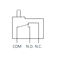
|
Related Information
CONTACT US
If you have any questions, please select the option below to contact us or find answers.
CONTACT US
BY EMAIL
BY EMAIL
Please click your area to select country or region
BY PHONE
- U.S.A.
- +1-800-344-2112
- Europe
- +49-89-45354-1000
- China
- +86-10-59255988
- Singapore
- +65-6299-9181


Related Information
FA Sensors & Components
Service & Support
Requests to customers (Automation Control Components & Industrial Device) [Excluding specific product]
Requests to customers (Automation Control Components & Industrial Device) [For specific product]
Requests to customers (FA Sensors & Components [Excluding motors])
Requests to customers (Dedicated to industrial motors)
- COMPONENTS & DEVICES
- FA SENSORS & COMPONENTS
- Fiber Sensors
- Photoelectric Sensors / Laser Sensors
- Micro Photoelectric Sensors
- Light Curtains / Safety Components
- Area Sensors
- Inductive Proximity Sensors
- Particular Use Sensors
- Sensor Options
- Wire-Saving Systems
- Programmable Controllers / Interface Terminal
- Human Machine Interface
- Pressure Sensors / Flow Sensors
- Measurement Sensors
- Static Control Devices
- Laser Markers / 2D Code Readers
- Machine Vision System
- Energy Management Solutions
- Timers / Counters / FA Components
- MOTORS
![]()