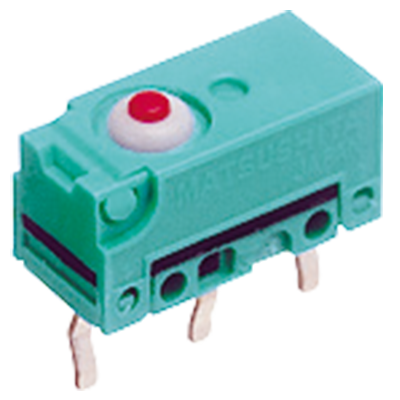
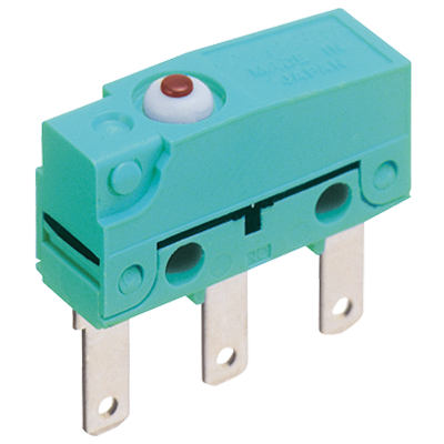
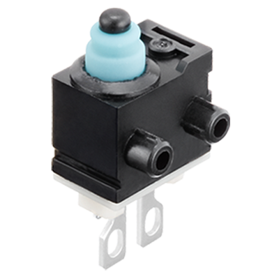
Turquoise Stroke Switches
1.Terminal type: Mounting hole 3 mm, standard type Pin plunger
- External dimensions
-
| Operating Force (OF) Max. |
1.5 N |
| Total travel Force (TF) Max. (reference
value) |
(2.0 N) |
| Free Position (FP) Max. |
From mounting boss
and hole center line |
9.2 mm |
| From standoff |
13.4 mm |
| Operating Position on N.C. side (OP (N.C.) ) |
From mounting boss
and hole center line |
8.7±0.3 mm |
| From standoff |
12.9±0.3 mm |
| Operating Position on N.O. side (OP (N.O.) ) |
From mounting boss
and hole center line |
8.4±0.3 mm |
| From standoff |
12.6±0.3 mm |
| Release Position on N.C. side (RP (N.C.) ) |
From mounting boss
and hole center line |
8.8±0.3 mm |
| From standoff |
13.0±0.3 mm |
| Release Position on N.O. side (RP (N.O.) ) |
From mounting boss
and hole center line |
8.5±0.3 mm |
| From standoff |
12.7±0.3 mm |
| Over travel on N.C. side (OT (N.C.) ) Min. |
2.5 mm |
| Over travel on N.O. side (OT (N.O.) ) Min. |
2.2 mm |
| Total Travel Position (TTP) (reference value) |
From mounting boss
and hole center line |
(5.9 mm) |
| From standoff |
(10.1 mm) |
|
Return to top
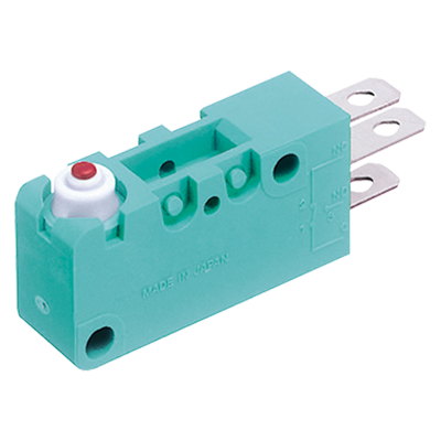
2.Terminal type: Leaf lever
- External dimensions
-
| * | When switching at high speed or under shock, lever endurance may drop. Therefore, please be sure to conduct an endurance evaluation under actual switching conditions. |
|---|
| Operating Force (OF) Max. |
1.7 N |
| Total travel Force (TF) Max. (reference value) |
(3.1 N) |
| Free Position (FP) Max. |
From mounting boss
and hole center line |
11.5 mm |
| From standoff |
15.7 mm |
| Operating Position on N.C. side (OP (N.C.) ) |
From mounting boss
and hole center line |
9.8±0.5 mm |
| From standoff |
14.0±0.5 mm |
| Operating Position on N.O. side (OP (N.O.) ) |
From mounting boss
and hole center line |
9.3±0.5 mm |
| From standoff |
13.5±0.5 mm |
| Release Position on N.C. side (RP (N.C.) ) |
From mounting boss
and hole center line |
10.1±0.5 mm |
| From standoff |
14.3±0.5 mm |
| Release Position on N.O. side (RP (N.O.) ) |
From mounting boss
and hole center line |
9.6±0.5 mm |
| From standoff |
13.8±0.5 mm |
| Over travel on N.C. side (OT (N.C.) ) Min. |
3.1 mm |
| Over travel on N.O. side (OT (N.O.) ) Min. |
2.6 mm |
| Total Travel Position (TTP) (reference value) |
From mounting boss
and hole center line |
(6.2 mm) |
| From standoff |
(10.4 mm) |
|
Return to top
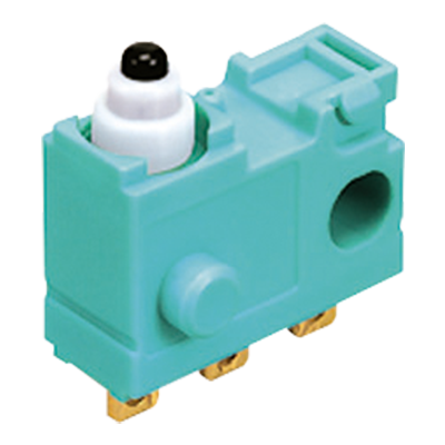
3.Terminal type: Simulated leaf lever
- External dimensions
-
| * | When switching at high speed or under shock, lever endurance may drop. Therefore, please be sure to conduct an endurance evaluation under actual switching conditions. |
|---|
| Operating Force (OF) Max. |
1.5 N |
| Total travel Force (TF) Max. (reference value) |
(2.8 N) |
| Free Position (FP) Max. |
From mounting boss
and hole center line |
14.4 mm |
| From standoff |
18.6 mm |
| Operating Position on N.C. side (OP (N.C.) ) |
From mounting boss
and hole center line |
12.5±0.5 mm |
| From standoff |
16.7±0.5 mm |
| Operating Position on N.O. side (OP (N.O.) ) |
From mounting boss
and hole center line |
12.0±0.5 mm |
| From standoff |
16.2±0.5 mm |
| Release Position on N.C. side (RP (N.C.) ) |
From mounting boss
and hole center line |
12.9±0.5 mm |
| From standoff |
17.1±0.5 mm |
| Release Position on N.O. side (RP (N.O.) ) |
From mounting boss
and hole center line |
12.4±0.5 mm |
| From standoff |
16.6±0.5 mm |
| Over travel on N.C. side (OT (N.C.) ) Min. |
3.3 mm |
| Over travel on N.O. side (OT (N.O.) ) Min. |
2.8 mm |
| Total Travel Position (TTP) (reference value) |
From mounting boss
and hole center line |
(8.7 mm) |
| From standoff |
(12.9 mm) |
|
Return to top
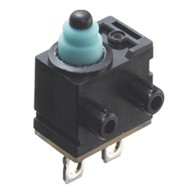
4.P/C board terminal: Mounting hole 3 mm without boss type
- P/C board terminal
-
|
- P/C board pattern
-
|
Return to top
5.Terminal type: Right side pin type
Return to top
6.Terminal type: Left side pin type
Return to top
7.Terminal type: Right 2 boss type
Return to top
8.Terminal type: Left 2 boss type
Return to top
9.Angle terminal type: Mounting hole 3 mm, standard type (Right type)
Return to top
10.Angle terminal type: Mounting hole 3 mm, standard type (Left type)
Return to top
11.Wire leads bottom type: Mounting hole 3 mm, standard type
- External dimensions
-
| *1 | Wire lead thickness: 0.3 mm2 |
|---|
| *2 |
| Wire lead color |
: |
COM ... Black |
| : |
N.O. ... White |
| : |
N.C. ... Red |
|
|---|
|
Return to top
12.Wire leads right side type: Mounting hole 3 mm, standard type
- External dimensions
-
| *1 | Wire lead thickness: 0.3 mm2 |
|---|
| *2 |
| Wire lead color |
: |
COM ... Black |
| : |
N.O. ... White |
| : |
N.C. ... Red |
|
|---|
|
Return to top
13.Wire leads left side type: Mounting hole 3 mm, standard type
- External dimensions
-
| *1 | Wire lead thickness: 0.3 mm2 |
|---|
| *2 |
| Wire lead color |
: |
COM ... Black |
| : |
N.O. ... White |
| : |
N.C. ... Red |
|
|---|
|
Return to top
Return to top

 Business
> Industrial Devices
> Automation Controls Top
> Components & Devices
> Switches
> Seal Type Switches
> Turquoise Stroke Switches
> Dimensions
Business
> Industrial Devices
> Automation Controls Top
> Components & Devices
> Switches
> Seal Type Switches
> Turquoise Stroke Switches
> Dimensions
 ABJ (BJ) Turquoise Switches
Ultra-miniature Size Sealed Switches
ABJ (BJ) Turquoise Switches
Ultra-miniature Size Sealed Switches
 ABS (BS) Turquoise Switches
Subminiature Size Sealed Switches
ABS (BS) Turquoise Switches
Subminiature Size Sealed Switches
 ABV (BV) Turquoise Switches
Miniature Size Sealed Switches
ABV (BV) Turquoise Switches
Miniature Size Sealed Switches
 Turquoise Stroke Switches
Long Stroke and Sliding Contact Construction Sealed Switches
Turquoise Stroke Switches
Long Stroke and Sliding Contact Construction Sealed Switches
 Turquoise Stroke Mini Switches
Small size and Long Stroke Sliding Contact Construction Sealed Switches
Turquoise Stroke Mini Switches
Small size and Long Stroke Sliding Contact Construction Sealed Switches
 Turquoise Stroke Mini Switch Resistor installed type
Small seal switches with wiring failure detecting function
Turquoise Stroke Mini Switch Resistor installed type
Small seal switches with wiring failure detecting function