【Notification of Manufacturer Change for Panasonic Industrial Devices SUNX Products and Panasonic Industrial Devices SUNX Tatsuno Products】
From April 1, 2024, the terms "Panasonic Industrial Devices SUNX Co., Ltd." and "Panasonic Industrial Devices SUNX Tatsuno Co., Ltd."
in this page and in the manuals and other documents to be downloaded will all be replaced with "Panasonic Industry Co., Ltd." and applied accordingly.

 Business
> Industrial Devices
> Automation Controls Top
> FA Sensors & Components
> Timers / Counters / FA Componets
> Timers
> LT4H Digital Timers(DIN 48)(Discontinued Products)
Business
> Industrial Devices
> Automation Controls Top
> FA Sensors & Components
> Timers / Counters / FA Componets
> Timers
> LT4H Digital Timers(DIN 48)(Discontinued Products)
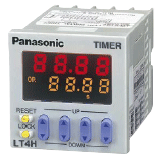
LT4H Digital Timers(DIN 48) (Discontinued Products)
|
We are sorry, the products have been discontinued. Please refer to the details of the discontinued products and the recommended substitutes list below.
|
|
Easy-to-read, user-friendly
digital timers with a short body developed to meet market needs
|


Recommended Substitutes
| Discontinued product | Recommended substitute | ||||
|---|---|---|---|---|---|
| Product number/Part number | Last time buy | Product number/Part number | Product name | Remark | |
| Product number: LT4HT-AC24V Part number: ATL5100 |
August 31, 2023 To be discontinued |
 |
Product number:- Part number:- |
- | Sorry, no suggested alternative products.
December 28, 2022 To be discontinued |
| Product number: LT4HT-DC24V Part number: ATL5101 |
August 31, 2023 To be discontinued |
|
Product number:- Part number:- |
- | Sorry, no suggested alternative products.
December 28, 2022 To be discontinued |
| Product number: LT4HT-AC240V Part number: ATL5107 |
August 31, 2023 To be discontinued |
|
Product number:- Part number:- |
- | Sorry, no suggested alternative products.
December 28, 2022 To be discontinued |
| Product number: LT4H-AC24V Part number: ATL5110 |
August 31, 2023 To be discontinued |
|
Product number:- Part number:- |
- | Sorry, no suggested alternative products.
December 28, 2022 To be discontinued |
| Product number: LT4H-DC24V Part number: ATL5111 |
August 31, 2023 To be discontinued |
|
Product number:- Part number:- |
- | Sorry, no suggested alternative products.
December 28, 2022 To be discontinued |
| Product number: LT4H-AC240V Part number: ATL5117 |
August 31, 2023 To be discontinued |
|
Product number:- Part number:- |
- | Sorry, no suggested alternative products.
December 28, 2022 To be discontinued |
| Product number: LT4HT8-AC24V Part number: ATL5120 |
August 31, 2023 To be discontinued |
|
Product number:- Part number:- |
- | Sorry, no suggested alternative products.
December 28, 2022 To be discontinued |
| Product number: LT4HT8-DC24V Part number: ATL5121 |
August 31, 2023 To be discontinued |
|
Product number:- Part number:- |
- | Sorry, no suggested alternative products.
December 28, 2022 To be discontinued |
| Product number: LT4HT8-AC240V Part number: ATL5127 |
August 31, 2023 To be discontinued |
|
Product number:- Part number:- |
- | Sorry, no suggested alternative products.
December 28, 2022 To be discontinued |
| Product number: LT4H8-AC24V Part number: ATL5130 |
August 31, 2023 To be discontinued |
|
Product number:- Part number:- |
- | Sorry, no suggested alternative products.
December 28, 2022 To be discontinued |
| Product number: LT4H8-DC24V Part number: ATL5131 |
August 31, 2023 To be discontinued |
|
Product number:- Part number:- |
- | Sorry, no suggested alternative products.
December 28, 2022 To be discontinued |
| Product number: LT4H8-AC240V Part number: ATL5137 |
August 31, 2023 To be discontinued |
|
Product number:- Part number:- |
- | Sorry, no suggested alternative products.
December 28, 2022 To be discontinued |
| Product number: LT4HT-AC24VS Part number: ATL5170 |
August 31, 2023 To be discontinued |
|
Product number:- Part number:- |
- | Sorry, no suggested alternative products.
December 28, 2022 To be discontinued |
| Product number: LT4HT-DC24VS Part number: ATL5171 |
August 31, 2023 To be discontinued |
|
Product number:- Part number:- |
- | Sorry, no suggested alternative products.
December 28, 2022 To be discontinued |
| Product number: LT4HT-AC240VS Part number: ATL5177 |
August 31, 2023 To be discontinued |
|
Product number:- Part number:- |
- | Sorry, no suggested alternative products.
December 28, 2022 To be discontinued |
| Product number: LT4H-AC24VS Part number: ATL5180 |
August 31, 2023 To be discontinued |
|
Product number:- Part number:- |
- | Sorry, no suggested alternative products.
December 28, 2022 To be discontinued |
| Product number: LT4H-DC24VS Part number: ATL5181 |
August 31, 2023 To be discontinued |
|
Product number:- Part number:- |
- | Sorry, no suggested alternative products.
December 28, 2022 To be discontinued |
| Product number: LT4H-AC240VS Part number: ATL5187 |
August 31, 2023 To be discontinued |
|
Product number:- Part number:- |
- | Sorry, no suggested alternative products.
December 28, 2022 To be discontinued |
Recommended Substitutes for Accessories/Options
| Discontinued product | Recommended substitute | |||||
|---|---|---|---|---|---|---|
| Product name | Product number/Part number | Last time buy | Product number/Part number | Product name | Remark | |
| 8P cap | Product number: AD8-RC Part number: AD8013 |
September 29, 2023 | |
Product number:- Part number:- |
- | Sorry, no suggested alternative products. |
| Protective cover for DIN 48 size | Product number: AQM4803 Part number: AQM4803 |
September 30, 2021 | |
Product number:- Part number:- |
- | Sorry, no suggested alternative products. |
| Rear terminal socket | Product number: AT8-R8K Part number: AT78041 |
September 29, 2023 | |
Product number:- Part number:- |
- | Sorry, no suggested alternative products. |
| Rear terminal socket | Product number: AT8-R11K Part number: AT78051 |
September 29, 2023 | |
Product number:- Part number:- |
- | Sorry, no suggested alternative products. |
| Mounting rails | Product number: AT8-DLA1 Part number: ATA48011 |
September 29, 2023 | |
Product number:- Part number:- |
- | Sorry, no suggested alternative products. |
| Fastening plate | Product number: AT8-DLE Part number: ATA4806 |
September 29, 2023 | |
Product number:- Part number:- |
- | Sorry, no suggested alternative products. |
| Mounting frame | Product number: AT8-DA4 Part number: ATA4811 |
September 29, 2023 | |
Product number:- Part number:- |
- | Sorry, no suggested alternative products. |
| 11P cap | Product number: AT8-DP11 Part number: ATA4861 |
September 29, 2023 | |
Product number:- Part number:- |
- | Sorry, no suggested alternative products. |
| Rubber gasket | Product number: ATC18002 Part number: ATC18002 |
September 29, 2023 | |
Product number:- Part number:- |
- | Sorry, no suggested alternative products. |
| DIN rail terminal socket | Product number: AT8-DF8K Part number: ATC180031 |
September 29, 2023 | |
Product number:- Part number:- |
- | Sorry, no suggested alternative products. |
| DIN rail terminal socket | Product number: AT8-DF11K Part number: ATC180041 |
September 29, 2023 | |
Product number:- Part number:- |
- | Sorry, no suggested alternative products. |
| Panel cover (Black) | Product number: ATL58011 Part number: ATL58011 |
September 29, 2023 | |
Product number:- Part number:- |
- | Sorry, no suggested alternative products. |
|
BY EMAIL
- U.S.A.
- +1-800-344-2112
- Europe
- +49-89-45354-1000
- China
- +86-10-59255988
- Singapore
- +65-6299-9181


Requests to customers (Automation Control Components & Industrial Device) [Excluding specific product]
Requests to customers (Automation Control Components & Industrial Device) [For specific product]
Requests to customers (FA Sensors & Components [Excluding motors])
Requests to customers (Dedicated to industrial motors)
- COMPONENTS & DEVICES
- FA SENSORS & COMPONENTS
- Fiber Sensors
- Photoelectric Sensors / Laser Sensors
- Micro Photoelectric Sensors
- Light Curtains / Safety Components
- Area Sensors
- Inductive Proximity Sensors
- Particular Use Sensors
- Sensor Options
- Wire-Saving Systems
- Programmable Controllers / Interface Terminal
- Human Machine Interface
- Pressure Sensors / Flow Sensors
- Measurement Sensors
- Static Control Devices
- Laser Markers / 2D Code Readers
- Machine Vision System
- Energy Management Solutions
- Timers / Counters / FA Components
- MOTORS
![]()