【Notification of Manufacturer Change for Panasonic Industrial Devices SUNX Products and Panasonic Industrial Devices SUNX Tatsuno Products】
From April 1, 2024, the terms "Panasonic Industrial Devices SUNX Co., Ltd." and "Panasonic Industrial Devices SUNX Tatsuno Co., Ltd."
in this page and in the manuals and other documents to be downloaded will all be replaced with "Panasonic Industry Co., Ltd." and applied accordingly.

 Business
> Industrial Devices
> Automation Controls Top
> FA Sensors & Components
> Energy Management Solutions
> Communication Devices
> KR20 Wireless Unit
> Cautions For Use
Business
> Industrial Devices
> Automation Controls Top
> FA Sensors & Components
> Energy Management Solutions
> Communication Devices
> KR20 Wireless Unit
> Cautions For Use
KR20 Wireless Unit
|
Discontinued
|
Cautions For Use
1.When mounting, (wiring, adjustment etc.), be careful not to add static electricity to connector, switch and antenna.
2.Do not squeeze the switches or push buttons with an excessive force. Otherwise, they may be damaged.
Mounting
- 1.Do not place the units in the vicinity of radios or TVs. Otherwise, the reception may be impaired.
- 2.If nearby broadcasting or wireless stations emit radio waves with a high field intensity, then this wireless system may not be used.
- 3.This system uses frequencies on 2.4 GHz band for data communication. If there are other devices using the same frequency band in its vicinity, then the communication may be impaired due to interference.
- 4.In order to make the wireless performance better, pay attention to the below items.
- Mount the unit as high as possible.
- Connect 2 of the antenna and the mounting direction is vertical for the ground.
- Antenna should be keep away from metal board. If antennas are mounted inside the control board, the wireless performance will decrease.
- Keep away from the place or line that noise might occur.
- Mount in the place where electric wave condition is good refer to field intensity monitor.
- When using several channels in the same communication area, check if there is no influence each other.
- 5.When mounting the unit to DIN rail, hook the upper part and push DIN hook. When removing it, pull out with minus driver until locking DIN hook. And fastening plate (ATA4806) is recommended to prevent from moving.
Restrictions
Wired communication restrictions
|
|
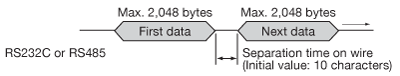
・Command and response sequence
If commands are sent in succession, then define a sequence, in which a command is sent after the response to the previous command is returned. If a time-out is defined, then the time required for wireless communication must be taken into consideration. The time required for wireless communication may be extended depending on the communication environment. If the interval between two commands is fixed, then a command and a response may collide with each other.
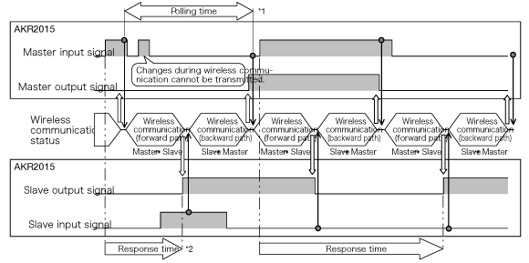
Input signal time
|
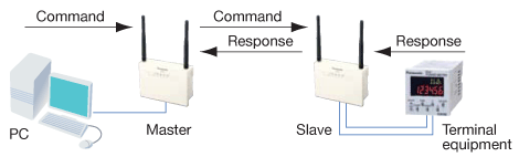
Protocol for 1:N topology
| Communication protocol | RS485 type | I/O type | Restrictions | Remark |
|---|---|---|---|---|
MEWTOCOL (Panasonic Electric Works) |
Yes | Yes | • The volume of data to be simultaneously transmitted must not exceed 2,048 bytes. • The time-out must be able to be extended. |
*1 |
| MODBUS ASCII | Yes | - | ||
| MODBUS RTU | Yes | - | ||
| GT Series Original | Yes | - | Screens cannot be transferred. | |
| Message Runner Original | Yes | - | Screens cannot be transferred. |
| *1 | Operations using the PLC software are not supported. |
|---|---|
| *2 | Use with 1:1 topology or 1:1 topology with repeaters for other protocols. |
To prevent from interference with the other wireless station (Japan only)
In the frequency band using this unit, in-plant radio station (license is necessary.) using at industrial such as microwave oven, science, medical machinery and a production line in factory to identify mobile object, specified low power radio station (license is not necessary.) and amateur radio station (license is necessary.) are managed
- 1.Before using this unit, please confirm that in-plant radio station to identify mobile object, specified low power radio station and amateur radio station are not managed.
- 2.When some cases of harmful electric wave interference occurred from this unit to an in-plant radio station to identify mobile object, change the using frequency immediately or stop discharging the electric wave. After that please contact us to consult measures to avoid interference (for example, setting of partition).
- 3.When any other troubles such as harmful electric wave interference occurred from this unit to a specified low power radio station or an amateur radio station or an amateur radio station, please contact us.
Actual indication
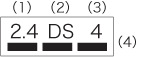 * Please put the attached label “Caution for using wireless unit” near the setting place. |
|
Countries where the use of KR20 has been authorized
[Note] Countries where the use of KR20 has been authorized
Products with the ![]() indication label affixed to their rear side As of May 2008, the use of KR20 has been authorized in the following countries:
indication label affixed to their rear side As of May 2008, the use of KR20 has been authorized in the following countries:
Japan, China*1, Thailand, 25 European countries (Austria, Belgium, Czech Republic, Denmark, Estonia, Finland, France*2, Germany, Greece, Hungary, Iceland, Ireland, Italy, Lithuania, Malta, Norway, Poland, Portugal, Slovakia, Slovenia, Spain, Sweden, Switzerland, UK, Netherlands)
| *1 | From March 31, 2013, this product will not be available in China. |
|---|---|
| *2 | In France, this product must not be used outdoors. Please use it indoors only. |
Compliance for EN standard
Obtained the European wireless certification (EN300 328)
In order to comply with EN standard, use this product in following condition.
・ When installing this product to wall, install it on a DIN rail.
・ Use power supply cord that is less than 3m.
・ For communication cable (RS232C or RS485), use shielded cable, and connect one end of shield wire to ground. And use ferrite core (correspond to TDK: ZCAT2035-0930) in the communication cable (RS232C or RS485) of wireless unit side. (Turn numbers: 2T)
BY EMAIL
- U.S.A.
- +1-800-344-2112
- Europe
- +49-89-45354-1000
- China
- +86-10-59255988
- Singapore
- +65-6299-9181


Requests to customers (Automation Control Components & Industrial Device) [Excluding specific product]
Requests to customers (Automation Control Components & Industrial Device) [For specific product]
Requests to customers (FA Sensors & Components [Excluding motors])
Requests to customers (Dedicated to industrial motors)
- COMPONENTS & DEVICES
- FA SENSORS & COMPONENTS
- Fiber Sensors
- Photoelectric Sensors / Laser Sensors
- Micro Photoelectric Sensors
- Light Curtains / Safety Components
- Area Sensors
- Inductive Proximity Sensors
- Particular Use Sensors
- Sensor Options
- Wire-Saving Systems
- Programmable Controllers / Interface Terminal
- Human Machine Interface
- Pressure Sensors / Flow Sensors
- Measurement Sensors
- Static Control Devices
- Laser Markers / 2D Code Readers
- Machine Vision System
- Energy Management Solutions
- Timers / Counters / FA Components
- MOTORS
![]()