【Notification of Manufacturer Change for Panasonic Industrial Devices SUNX Products and Panasonic Industrial Devices SUNX Tatsuno Products】
From April 1, 2024, the terms "Panasonic Industrial Devices SUNX Co., Ltd." and "Panasonic Industrial Devices SUNX Tatsuno Co., Ltd."
in this page and in the manuals and other documents to be downloaded will all be replaced with "Panasonic Industry Co., Ltd." and applied accordingly.

 Business
> Industrial Devices
> Automation Controls Top
> FA Sensors & Components
> Energy Management Solutions
> Eco Series (Simple Watt-Hour Meter/ Simple Power-On Counter/ Power-On Hour Meter)
> KW4M Eco-POWER METER(Discontinued Products)
> Rating/ Performance
Business
> Industrial Devices
> Automation Controls Top
> FA Sensors & Components
> Energy Management Solutions
> Eco Series (Simple Watt-Hour Meter/ Simple Power-On Counter/ Power-On Hour Meter)
> KW4M Eco-POWER METER(Discontinued Products)
> Rating/ Performance
KW4M Eco-POWER METER (Discontinued Products)
|
We are sorry, the products have been discontinued. Please refer to the details of the discontinued products and the recommended substitutes list below.
|
Rating/ Performance
Measurement items
| Item | Unit | Data display range | |
|---|---|---|---|
| Instantaneous electrical power | kW | 0.00 to 9999.99 | |
| Integrated electrical energy | kWh MWh |
0.00 to 9999.99 kWh to | |
| 10.00 MWh to 9999.99 MWh | |||
| When 9-digit display: 0.00 to 9999999.99 kWh | |||
| Current | L1(CT1)phase current | A | 0.0 to 6000.0 |
| L2(CT2)phase current | A | 0.0 to 6000.0 | |
| Voltage | Voltage between 1-2 | V | 0.0 to 9999.9 |
| Voltage between 2-3 | V | 0.0 to 9999.9 | |
| Electricity charge (Note) |
Yen | JPY | 0 to 999999 |
| Dollars | $ | 0.0 to 99999.9 | |
| Euros | EUR | 0.0 to 99999.9 | |
| Yuan | CNY | 0 to 999999 | |
| No currency | CHG | 0 to 999999 | |
| Conversion carbon dioxide value | kg-CO2 | 0.0 to 999999 | |
| Hour meter | ON time | h(Hour) | 0.0 to 99999.9 |
| OFF time | h(Hour) | 0.0 to 99999.9 | |
| Pulse input | Count | 0 to 999999 | |
Note : Eco-POWER METER is designed chiefly to manage saving energy. It is neither intended nor can it be legally used for billing.
Main unit
| Rated operating voltage | 100-120/200-240V AC | |
|---|---|---|
| Rated frequency | 50/60 Hz common | |
| Rated power consumption | 8VA (240 V AC at +25 ℃ +77 ℉) | |
| Allowable operating voltage range | 85 to 132/170 to 264V AC (85% to 110% of rated operating voltage) | |
| Allowable momentary power-off time | 10ms | |
| Ambient temperature | -10 to +50 ℃ +14 to +122 ℉ (-25 to +70 ℃ -13 to +158 ℉ at storage) | |
| Ambient humidity | 30 to 85% RH (at +20℃ +68 ℉ non-condensing) | |
| Breakdown voltage (initial) | Between the isolated circuits: 2000 V for 1min | [Use as a power meter] ・ Insulated circuit [between (1) and (2), (2) and (3), (1) and (3)] (1) Power terminal [1 (R), 2 (N and S) and 3 (T)] CT input terminal [CT1 (+), CT2 (+) and CT1, 2 (-)] (2) RS485 terminal (+, -) (3) Pulse output terminal (+, -) ・ Outer edge (case) - all terminals [Use as a pulse counter] ・ Insulated circuit [between (1) and (2), (2) and (3), (1) and (3)] (1) Power terminal [1 (R) and 2 (N)], pulse input terminal [CT1 (+) and 0V] (2) RS485 terminal (+, -) (3) Pulse output terminal (+, -) ・ Outer edge (case) - all terminals |
| Insulation resistance (initial) | Between the isolated circuits: 100 MΩ or more (measured with 500 V DC) |
|
| Vibration resistance | 10 to 55 Hz (1cycle / min), single amplitude: 0.75 mm 0.03 in (1 hour on 3 axes) | |
| Shock resistance | Min. 294 m/s2 (5 times on 3 axes) | |
| Display method | 6-digit, 7-segment (set value) with backlight and 4-digit, 16-segment (mode), LCD upper section: green, lower section: amber | |
| Power failure memory method | EEPROM (more than 100,000 overwrite) | |
| Protection | IEC standard IP66 (only front panel with rubber gasket) * Mounted in a row, waterproofing property will be lost. |
|
| Weight | 140 g approx. (screw terminal type), 130 g approx. (11-pin type) | |
Input specifications
Power Input
| Phase and wire system | Single-phase two-wire system Single-phase three-wire system Three-phase three-wire system |
(common) | |
|---|---|---|---|
| Input voltage |
Rating | Single-phase two-wire : 100-120/200-240V AC (common) Single-phase three-wire : 100-120V AC Three-phase three-wire : 100-240V AC |
|
| Allowance | 85 to 110% of rated input voltage | ||
| Allowable measurement voltage | Single-phase two-wire : 85-132/170-264V AC (common) Single-phase three-wire : 85-132V AC Three-phase three-wire : 85-264V AC |
||
| VT ratio | 1.00 to 99.99 (Set with setting mode) *Voltage transformer (VT) is required when you measure a load with voltage over 240VAC (Allowable measurement voltage). *Secondary current rating of VT is 110V. |
||
| Input current |
Primary side rating | <Using the dedicated CT> ・5A/50A/100A/250A/400A (Select with setting mode) <Using a commercial CT with the secondary side current 5A> ・1 to 4000A (Set with setting mode) *Use a CT with secondary side current of 5A when measure 400A or more. |
|
| Special functions |
Cut-off current | 1.0 to 50.0%F.S | |
| Hour meter threshold current | 1.0 to 100.0%F.S | ||
| Accuracy (without error in CT and VT) |
Basic accuracy |
Instantaneous electric power, Integrated electric power, Electricity charge and Conversion value |
|
| Within ± (2.0 % F.S. + 1 digit) In case of 5 A CT mode. Within ± (2.5 % F.S. + 1 digit) (at +20 ℃ +68 ℉, rated input, rated frequency, power factor 1) Accuracy coverage: 5 to 100 % of rated current |
|||
| Current | |||
| Within ± (1.0 % F.S. + 1 digit) (at +20 ℃ +68 ℉ rated input, rated frequency, power factor 1) Accuracy coverage: 5 to 100 % of rated current | |||
| Voltage | |||
| Within ± (1.0 % F.S. + 1 digit) (at +20 ℃ +68 ℉ rated input, rated frequency, power factor 1) | |||
| Hour Meter | |||
| Within ± (0.01 % +1 digit) (at +20 ℃ +68 ℉) [In case power on start or current energizing: Within ± (0.01 % + 1 sec + 1 digit) (at +20 ℃ +68 ℉)] | |||
| Temperature characteristics | Within ± (1.0 % F.S. + 1 digit) In case of 5 A CT mode. Within ± (1.5 % F.S. + 1 digit) (Range of -10 to +50 ℃ +14 to +122 ℉, rated input, power factor 1) | ||
| Frequency characteristics | Within ± (1.0 % F.S. + 1 digit) In case of 5 A CT mode. Within ± (1.5 % F.S. + 1 digit) (Frequency change ± 5 % based on rated frequency, rated input, power factor 1) | ||
Pulse input
| Input mode | Addition (fixed) | |
|---|---|---|
| Max. counting speed | 2 kHz/30 Hz (selectable by mode) | |
| Pulse input | Min. input signal width: 0.25 ms (when 2 kHz selected)/16.7 ms (when 30 Hz selected) ON : OFF ratio = 1 : 1 | |
| Input signal | Contact/No contact (open collector) · Impedance when shorted: 1kohm · Residual voltage when shorted: Max. 2 V · Impedance when open: 100kohm |
|
| Output mode | HOLD (over count) | |
| Number of digits | 6 digits display (0 to 999999)(selectable by mode) | |
| Pre-scale setting | Decimal point | Set to 3rd decimal places (Auto-setting) |
| Range | 0.001 to 100.000 (Selectable with setting mode) | |
| Unit | 「CNT」/「l」/「kl」/「m3」 (Selectable with setting mode) (Count value does not change even if the unit setting is changed during counting.) |
|
Pulse output (transistor output)
| Number of output points | 1 point | |
|---|---|---|
| Insulation method | Optical coupler | |
| Output type | Open collector | |
| Output capacity | 100mA 30V DC | |
| Pulse width | Approx. 100ms | |
| ON state voltage drop | 1.5V or less | |
| OFF state leakage current | 100 µA or less | |
| Pulse output unit * | When measuring power | 0.001/0.01/0.1/1/10/100 kWh/Alarm (selectable by mode) |
| When measuring pulse input | HOLD (over count) | |
* Power and pulse input are not possible at the same time.
Communication
| Interface | Conforming to RS485 | |
|---|---|---|
| Protocol | MEWTOCOL/Modbus(RTU)(Depending on part number.) | |
| Isolation status | Isolated with the internal circuit | |
| Number of connected units | 99 (max.) (Note1) (Note2) | |
| Transmission distance | 1200m | |
| Transmission speed | 38400/19200/9600/4800/2400bps (selectable with setting mode) | |
| Transmission Format | Data length | 8bit/7bit (selectable with setting mode) (MEWTOCOL type) 7bit (fixed) (MODBUS type) |
| Parity | Not available/Odd number/Even number (selectable with setting mode) |
|
| Stop bit | 1bit(fixed) | |
| Communication method | Half-duplex | |
| Synchronous system | Synchronous communication method | |
| Ending resistance | Approx. 120Ω(built-in)(Note3) | |
| Note 1: | For RS-485 converter on the computer side, we recommend SI-35 (from LINE EYE Co.,Ltd.). |
| Note 2: | When using SI-35, SI-35USB or PLC from our company (which can be connected up to 99 units), up to 99 Eco-POWER METER can be connected.In case using this system with the other devices, up to 31 Eco-POWER METER can be connected. |
| Note 3: | Change the sliding switch of main unit as a terminal station. (Factory setting; General side) |
Recommended cable
Use the transmission cables shown below for Eco-POWER METER RS485 communication system.
| Cable | Conductor | Insulator | Cable diameter |
Applicable cable | ||
|---|---|---|---|---|---|---|
| Size | Resistance (at 20℃) |
Material | Thickness | |||
| Twisted-pair with shield |
1.25 mm2 0.0019 in2 (AWG16) or more |
Max. 16.8 Ω / km | polyethylene | Max. 0.5 mm 0.020 in |
Approx. 8.5 mm 0.335 in |
HITACHI KPEV-S1.25 mm2 0.0019 in2 × 1P Belden Inc.9860 |
| 0.5 mm2 0.0008 in2 (AWG20) or more |
Max. 33.4 Ω / km | polyethylene | Max. 0.5 mm 0.020 in |
Approx. 7.8 mm 0.307 in |
HITACHI KPEV-S0.5 mm2 0.0008 in2 × 1P Belden Inc.9207 |
|
| VCTF | 0.75 mm2 0.0012 in2 (AWG18) or more |
Max. 25.1 Ω / km | PVC | Max. 0.6 mm 0.024 in |
Approx. 6.6 mm 0.260 in |
VCTF0.75 mm2 0.0012 in2 × 2C(JIS) |
| Cable | Twisted-pair with shield | VCTF |
|---|---|---|
| section | 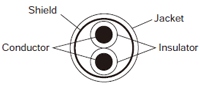 |
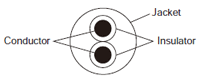 |
| Note 1) | Use shielded type twist cables. |
| Note 2) | Use only one type of the transmission cables. Do not mix different types of the cables. |
| Note 3) | Use twist pair cables under a bad noise environment. |
DEDICATED CURRENT TRANSFORMER (CT)
Specifications
| Item | Clamp-on typ | ||||
|---|---|---|---|---|---|
| AKW4801B AKW4801C |
AKW4802B AKW4802C |
AKW4803B AKW4803C |
AKW4804B AKW4804C |
AKW4808B AKW4808C |
|
| CE marking directive compliance | Low Voltage Directive, RoHS Directive | ||||
| Primary side rated current | 5A/50A | 100A | 250A | 400A | 600A |
| Secondary side rated current | 1.67mA/16.7mA | 33.3mA | 125mA | 200mA | 200mA |
| Winding (Turn) | 3000 | 3000 | 2000 | 2000 | 3000 |
| Ratio error | ±2.0%F.S. | ||||
| Through hole | ø10 ø0.39 | ø16 ø0.63 | ø24 ø0.94 | ø36 ø1.42 | ø36 ø1.42 |
| Breakdown voltage (initial) | 1000V AC/1min (Between through hole and output lead wire) |
2000V AC/1min (Between through hole and output lead wire) |
|||
| Insulation resistance (initial) | Min. 100 M Ω (at 500 V DC) (Between through hole and output lead wire) | ||||
| Functional vibration resistance | 10 to 55 Hz (1 cycle / min), single amplitude: 0.15 mm 0.01 in (10 min on 3 axes) | ||||
| Vibration resistance | 10 to 55 Hz (1 cycle / min), single amplitude: 0.375 mm 0.01 in (1 hour on 3 axes) | ||||
| Functional shock resistance | Min. 98m/s2(4 times on 3 axes) | ||||
| Shock resistance | Min. 294m/s2(5 times on 3 axes) | ||||
| Output protection level | ±7.5 V with clamp element | ±3.0V with clamp element | |||
| Permissible clamping frequency | 100 times approx. | ||||
| Ambient temperature range | -10 to +50℃ +14 to +122 ℉ (without frost and non-condensing) | ||||
| Storage temperature | -20 to +60℃ -4 to +140 ℉ (without frost and non-condensing) | ||||
| Ambient humidity | 35 to 85%RH(at +20℃ +68 ℉ non-condensing) | ||||
| Dimensions (mm in) (W x H x D) |
23 x 40 x 26.5 0.08 x 0.13 x 0.09 |
30 x46.5 x 32 0.10 x 0.15 x 0.11 |
45 x65 x 34 0.15 x 0.21 x 0.11 |
57 x81 x 38 0.19 x 0.27 x 0.12 |
62.6 x93.3 x 40 0.21 x 0.31 x 0.13 |
| Weight (Relay cable included) |
60 g approx. | 90 g approx. | 200 g approx. | 295 g approx. | 450 g approx. |
| Item | Through type | |||
|---|---|---|---|---|
| AKW4506B AKW4506C |
AKW4507B AKW4507C |
AKW4508B AKW4508C |
||
| CE marking directive compliance | Low Voltage Directive, RoHS Directive | |||
| Primary side rated current | 50A/100A | 250A/400A | 600A | |
| Secondary side rated current | 16.7mA/33.3mA | 125mA/200mA | 200mA | |
| Winding (Turn) | 3000 | 2000 | 3000 | |
| Ratio error | ±1.0%F.S. | |||
| Through hole | ø17mm ø0.67 in | ø36mm ø1.42 in | ||
| Breakdown voltage (initial) | 1000V AC/1min (Between through hole and output lead wire)) |
2000V AC/1min (Between through hole and output lead wire) |
||
| Insulation resistance (initial) | Min. 100 MΩ (at 500 V DC megger) (Between through hole and output lead wire) | |||
| Functional vibration resistance | 10 to 55 Hz (1 cycle / min), single amplitude: 0.15 mm 0.01 in (10 min on 3 axes) | |||
| Vibration resistance | 10 to 55 Hz (1 cycle / min), single amplitude: 0.375 mm 0.01 in (1 hour on 3 axes) | |||
| Functional shock resistance | Min. 98 m/s2 (4 times on 3 axes) | |||
| Shock resistance | Min. 294 m/s2 (5 times on 3 axes) | |||
| Output protection level | ±7.5 V with clamp element | ±3.0 V with clamp element | ||
| Permissible clamping frequency | - | |||
| Ambient temperature range | –10 to +50 ℃ +14 to +122 ℉ (without frost and non-condensing) | |||
| Storage temperature | –20 to +60 ℃ –4 to +140 ℉ (without frost and non-condensing) | |||
| Ambient humidity | 35 to 80 % RH (at +20 ℃ +68 ℉non-condensing) | |||
| Dimensions (mm in) (W x H x D) |
ø42 x 15 1.65 x 0.05 |
ø70 x19 2.76 x 0.06 |
ø70 x19 2.76 x 0.06 |
|
| Weight (Relay cable included) |
70 g approx. | 200 g approx. | 215 g approx. | |
Notes :
| 1) | Dedicated CT are dedicated for low voltage under 440 V AC system. They can not be used for high voltage circuit. |
|---|---|
| 2) | In each type of Eco-POWER METER excluding AKW8115, KW9M and KW2M, a combination of commercially secondary side 5 A CTs and dedicated CTs for 5 A is used for measuring high voltage circuits; For details, confirm with each respective user's manual. |
| 3) | Since dedicated CTs cannot be used when measuring with AKW8115, KW9M and KW2M, please be careful and do not purchase a dedicated CT by mistake. |
| 4) | For the AKW8115, KW9M and KW2M, CT with a secondary side current 1 A or 5 A is recommended. Please confirm the specification beforehand. |
| 5) | Dedicated CT are not included with Eco-POWER METERs. |
| 6) | Each dedicated CT includes a 1 m 3.281 ft relay cable, respectively. |
BY EMAIL
- U.S.A.
- +1-800-344-2112
- Europe
- +49-89-45354-1000
- China
- +86-10-59255988
- Singapore
- +65-6299-9181


Requests to customers (Automation Control Components & Industrial Device) [Excluding specific product]
Requests to customers (Automation Control Components & Industrial Device) [For specific product]
Requests to customers (FA Sensors & Components [Excluding motors])
Requests to customers (Dedicated to industrial motors)
- COMPONENTS & DEVICES
- FA SENSORS & COMPONENTS
- Fiber Sensors
- Photoelectric Sensors / Laser Sensors
- Micro Photoelectric Sensors
- Light Curtains / Safety Components
- Area Sensors
- Inductive Proximity Sensors
- Particular Use Sensors
- Sensor Options
- Wire-Saving Systems
- Programmable Controllers / Interface Terminal
- Human Machine Interface
- Pressure Sensors / Flow Sensors
- Measurement Sensors
- Static Control Devices
- Laser Markers / 2D Code Readers
- Machine Vision System
- Energy Management Solutions
- Timers / Counters / FA Components
- MOTORS
![]()