【Notification of Manufacturer Change for Panasonic Industrial Devices SUNX Products and Panasonic Industrial Devices SUNX Tatsuno Products】
From April 1, 2024, the terms "Panasonic Industrial Devices SUNX Co., Ltd." and "Panasonic Industrial Devices SUNX Tatsuno Co., Ltd."
in this page and in the manuals and other documents to be downloaded will all be replaced with "Panasonic Industry Co., Ltd." and applied accordingly.

 Business
> Industrial Devices
> Automation Controls Top
> FA Sensors & Components
> Measurement Sensors
> Measurement Sensors
> Thru-beam Type Digital Displacement Sensor HG-T
> Specifications
Business
> Industrial Devices
> Automation Controls Top
> FA Sensors & Components
> Measurement Sensors
> Measurement Sensors
> Thru-beam Type Digital Displacement Sensor HG-T
> Specifications
Thru-beam Type Digital Displacement Sensor HG-T
|
Specifications
Sensor heads
| Type | Measurement width 10 mm 0.394 in / Standard type | Measurement width 10 mm 0.394 in / Slim type | |
|---|---|---|---|
| Model No. | HG-T1010 | HG-T1110 | |
| Applicable regulations | CE Marking (EMC Directive, RoHS Directive), UKCA Marking (EMC Regulations, RoHS Regulations), FDA regulations | ||
| Compatible controller | HG-TC101 (-P), HG-TC111 (-P), HG-TC113 | ||
| Position detection method | CMOS-based | ||
| Installation distance | 0 to 500 mm 0 to 19.685 in | ||
| Measurement width | 10 mm 0.394 in | ||
| Light source | Red semiconductor laser: Class 1 [IEC / EN / JIS / GB / KS / FDA (Note 2)] Maximum output: 0.3 mW, Peak emission wavelength: 655 nm |
||
| Repeatability (Note 3) | 1 μm 0.039 mil (Installation distance: 20 mm 0.787 in) 2.5 μm 0.098 mil (Installation distance: 100 mm 3.937 in) 5 μm 0.197 mil (Installation distance: 500 mm 19.685 in) |
||
| Linearity (Note 4) | ±0.12 % F.S. (Installation distance: 20 mm 0.787 in) ±0.28 % F.S. (Installation distance: 100 mm 3.937 in) |
||
| Minimum sensing object (Note 5) | ø0.5 mm ø0.020 in (Installation distance: 500 mm 19.685 in) | ||
| Temperature characteristics (Note 6) | ±0.03 % F.S./℃ | ||
| Operation indicator | Emitter | Laser radiation indicator (Green) | |
| Receiver | Beam axis adjustment indicator (Orange / Green), Judgment output indicator (Orange / Green) |
Judgment output indicator (Orange / Green) | |
| Pollution degree | 2 | ||
| Operating altitude | 2,000 m 6,561.68 ft or less (Note 7) | ||
| Environmental resistance | Protection | IP67 (IEC) (Excluding connectors) | |
| Ambient temperature | -10 to +45 ℃ +14 to +113 ℉ (No dew condensation or icing allowed), Storage: -20 to +60 ℃ -4 to +140 ℉ | ||
| Ambient humidity | 35 to 85 % RH, Storage: 35 to 85 % RH | ||
| Ambient illuminance | Incandescent light: 5,000 lx or less at the light-receiving face (Note 8) | ||
| Insulation resistance | 20 MΩ or higher, using 250 V DC megger (between all terminals and case) | ||
| Vibration resistance | 10 to 55 Hz frequency, 1.5 mm 0.059 in double amplitude in X, Y and Z directions for two hours each | ||
| Shock resistance | 196 m/s2 acceleration in X, Y and Z directions three times each | ||
| Grounding method | Capacitor grounding | ||
| Material | Case: Die-cast aluminum, Light emitting and light receiving surfaces: Glass | ||
| Cable | 0.2 m 0.656 ft 4-core shielded cable with round connectors | ||
| Net weight | Emitter: 30 g approx., Receiver: 30 g approx. | Emitter: 30 g approx., Receiver: 25 g approx. | |
Notes:
| 1) | Specification values are based on the digital measurement values obtained by the sensor head and controller HG-TC□. Where measurement conditions have not been specified precisely, the conditions used were as follows: ambient temperature = +20 ℃ +68 ℉, controller’s average count setting 16 times, measurement target = nontransparent knife edge, installation distance = 100 mm 3.937 in, positional condition of measurement target = Half shading at the middle position of installation distance. |
|---|---|
| 2) | This product complies with the FDA regulations (FDA 21 CFR 1040.10 and 1040.11) in accordance with FDA Laser Notice No. 56, except for complying with IEC 60825-1 Ed. 3. |
| 3) | This is the P-P value of digital measurement value with half shading at the middle position of the installation distance. |
| 4) | Indicates an error with the ideal straight line of digital measured values. |
| 5) | When the light is blocked at the center position of 500 mm 19.685 in installation distance. |
| 6) | When the light is half-blocked at the center position of 100 mm 3.937 in installation distance. |
| 7) | Do not use or store in an environment that has been pressurized to an air pressure higher than the atmospheric pressure at 0 m. |
| 8) | When the sampling cycle of the controller is set to "standard sampling". |
Controller
| Type | Master unit | Slave unit | ||
|---|---|---|---|---|
| High performance type | High performance type | Wire-saving type | ||
| Model No. | NPN output | HG-TC101 | HG-TC111 | HG-TC113 |
| PNP output | HG-TC101-P | HG-TC111-P | ||
| Applicable regulations | CE Marking (EMC Directive, RoHS Directive), UKCA Marking (EMC Regulations, RoHS Regulations) | |||
| Compatible sensor head | HG-T1010、HG-T1110 | |||
| Number of connectable units | Up to 15 slave units can be connected to a master unit. (Note 2) | |||
| Supply voltage | 24 V DC ±10 %, including ripple 0.5 V (P-P) | |||
| Current consumption (Note 3) | 100 mA or less (when sensor head is connected) | |||
| Analog outputs (Switching type) (Note 4) |
Analog voltage output |
• Voltage output range: 1 to 5 V/F.S. (default value) • Linearity: ±0.05 % F.S. • Output when alarm occurs: 5.2 V • Output impedance: 100 Ω max. |
- | |
| Analog current output |
• Current output range: 4 to 20 mA/F.S. (default value) • Linearity: ±0.25 % F.S. • Output when alarm occurs: 0 mA • Load impedance: 250 Ω max. |
|||
| Control outputs (Output 1, Output 2, Output 3) |
<NPN output type> NPN open-collector transistor • Maximum sink current: 50 mA (Note 5) • Applied voltage: 30 V DC or less (between output and 0 V) • Residual voltage: 1.5 V or less (at 50 mA sink current) • Leakage current: 0.1 mA or less <PNP output type> PNP open-collector transistor • Maximum source current: 50 mA (Note 5) • Applied voltage: 30 V DC or less (between output and +V) • Residual voltage: 1.5 V or less (at 50 mA source current) • Leakage current: 0.1 mA or less |
- | ||
| Short-circuit protection | Incorporated (automatic reset type) | |||
| Judgment output | N.O. / N.C. switching type | |||
| Alarm output | Open when alarm occurs | |||
| External output switching | Output 1, Output 2, and Output 3 can be switched to 3-value, 2-value, Logic, and Logic 2. | - | ||
| External inputs (Input 1, Input 2, Input 3) |
<NPN output type> Non-contact input or NPN open-collector transistor • Input conditions Invalid: +8 V to +V DC or open Valid: 0 to +1.2 V DC • Input impedance: 10 kΩ approx. <PNP output type> Non-contact input or PNP open-collector transistor • Input conditions Invalid: 0 to +0.6 V DC or open Valid: +4 V to +V DC • Input impedance: 10 kΩ approx. |
- | ||
| Input time | • Trigger input: 2 ms or more (ON) • Laser emission stop input, preset input, reset input, bank input A/B(Note 6): 20 ms or more (ON) |
|||
| External input switching | Input 1, Input 2, and Input 3 can be switched to “Preset / Reset / Trigger”, “Bank Input A / Bank Input B / Select (Preset, Reset, Trigger)”, or “Laser emission stop”. | - | ||
| Sampling cycle | 1 ms (standard sampling) / 0.5 ms (high-speed sampling) | |||
| Average count (response time) (Note 6) |
1 time (2 ms), 2 times (3 ms), 4 times (5 ms), 8 times (9 ms), 16 times (17 ms), 32 times (33 ms), 64 times (65 ms), 128 times (129 ms), 256 times (257 ms), 512 times (513 ms), and 1,024 times (1,025 ms) switching type | |||
| Display resolution | 1 μm 0.039 mil | |||
| Display range | -199.999 to 199.999 mm -7.874 to 7.874 in | |||
| Interference prevention function | Incorporated (Note 7) | - | ||
| Pollution degree | 2 | |||
| Operating altitude | 2,000 m 6561.68 ft or less (Note 8) | |||
| Environmental resistance | Protection | IP40(IEC) | ||
| Ambient temperature | -10 to +50 ℃ +14 to +122 ℉ (No dew condensation or icing allowed) (Note 5), Storage: -20 to +60 ℃ -4 to +140 ℉ | |||
| Ambient humidity | 35 to 85 % RH, Storage: 35 to 85 % RH | |||
| Voltage withstandability | 1,000 V AC for one minute between all supply terminals connected together and enclosure | |||
| Insulation resistance | 20 MΩ, or more, with 250 V DC megger between all supply terminals connected together and enclosure | |||
| Vibration resistance | 10 to 150 Hz frequency, 0.75 mm 0.030 in double amplitude (10 to 58 Hz), Maximum acceleration 49 m/s2 (58 to 150 Hz) in X, Y and Z directions for two hours each | |||
| Shock resistance | 98m/s2 acceleration (10 G approx.) in X, Y and Z directions five times each | |||
| Material | Case: Polycarbonate, Cover: Polycarbonate, Switches: Polyacetal | |||
| Cable | 0.2 mm2 2-core (brown and blue lead wires) / 0.15 mm2 7-core composite cable, 2 m 6.562 ft long |
0.15 mm2 7-core composite cable, 2 m 6.562 ft long | - | |
| Net weight | 140 g approx. | 140 g approx. | 60 g approx. | |
Notes:
| 1) | Where measurement conditions have not been specified precisely, the conditions used were as follows: supply voltage +24 V DC, ambient temperature +20 ℃ +68 ℉. |
|---|---|
| 2) | When connected to a communication unit for digital displacement sensor, up to 14 slave units can be connected per master unit. |
| 3) | Current consumption does not include analog current output. |
| 4) | Linearity is a value calculated from digitally measured values at F.S. = 16 mA for current output or F.S. = 4 V for voltage output. |
| 5) | When slave units are connected to the master unit, the maximum sink current / source current of control output and ambient temperature vary depending on the number of connected slave units as shown below. |
| Number of connected slave units | Maximum sink current and source current of control output |
Ambient temperature | |
|---|---|---|---|
| When communication unit is connected | |||
| 1 to 7 units | 1 to 6 units | 20 mA | -10 to +45 ℃ +14 to +113 ℉ |
| 8 to 15 units | 7 to 14 units | 10 mA | |
| 6) | Average count (response time) is for when the sampling cycle is set to 1 ms (standard sampling). Response times differ when the sampling cycle is set to 0.5 ms (high-speed sampling). |
|---|---|
| 7) | This function operates for each set of 4 connected controllers.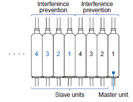 |
| 8) | Do not use or store in an environment that has been pressurized to an air pressure higher than the atmospheric pressure at 0 m. |
HG-T series' self-monitoring function
| Status | Response parameter | Measures | Controller HG-TC□ | |
|---|---|---|---|---|
| Error code (Note 1) |
Measurement alarm (Note 1) |
|||
| Notification | Sensor head unconnected | Status check | E200 | — |
| Connected sensor head incompatible | Status check | E230 | — | |
| Connected unit count check error | Status check | E160 (For master units only) |
— | |
| NPN / PNP output type mixture error | Status check | E100 (For master units only) |
— | |
| Calculated unlit count error | Status check | E110 (For master units only) |
— | |
| Copy executionerror (Slave unit problem) | Status check | E170 (For master units only) |
— | |
| Detection capability limit (obtained edge information) (Note 2) | Sensing object check | — | Measurement alarm 1 | |
| The amount of entering light is too much due to the influences of ambient light, etc. (Note 2) | Status check | — | Measurement alarm 1 | |
| The amount of entering light decreases due to stain on the detection surface, beam axis misalignment, etc. | Sensing object check | — | Measurement alarm 2 | |
| The specified measurement direction differs from the insertion direction of the detected object. | Status check / Sensing object check | — | Measurement alarm 2 | |
| Caution | Controller cumulative run time exceeded (87,600 hours) | Controller replacement | — | — |
| Sensor head cumulative run time exceeded (87,600 hours) | Sensor head replacement | — | — | |
| Controller memory saving count exceeded (1,000,000 times) | Controller replacement | — | — | |
| Sensor head memory saving count exceeded (for receivers only, 1,000,000 times) | Sensor head replacement | — | — | |
| Fault | Controller memory function damaged | Controller replacement | E600 | — |
| E610 | ||||
| E620 | ||||
| Sensor head memory function damaged | Sensor head replacement | E630(For receivers only) E640(For emitters only) |
— | |
| Output section short-circuit error | Status check / Replacement | E700 | — | |
| Detection circuit damaged | Sensor head replacement | E240 | — | |
| System error | Controller replacement | E900 | — | |
| E910 | ||||
| E911 | ||||
| E912 | ||||
| E920 | ||||
Notes:
| 1) | Error codes and alarms are displayed on HG-TC□ controllers. |
|---|---|
| 2) | If "Alarm condition selection (ALM.CND)" is set to "Hold last value (HOLD)", Measurement alarm 1 is not notified. |
Communication units for digital displacement sensors
| Designation | USB communication unit | |
|---|---|---|
| Model No. | SC-HG1-USB | |
| Regulatory compliance | CE Marking (EMC Directive, RoHS Directive), UKCA Marking (EMC Regulations, RoHS Regulations) | |
| Compatible controllers | HG-TC□ | |
| Maximum number of connectable controllers |
Maximum of 15 controllers (one master, 14 slaves) per SC‑HG1‑USB unit | |
| Supply voltage (Note 2) | 24 V DC ±10 %, Ripple (P-P) 10 % or less (Within specified power supply voltage range) |
|
| Current consumption | 50 mA or less | |
| Communication method | USB 2.0 Full Speed (Note 3) | |
| Communication protocol | Our dedicated protocol | |
| USB port | USB Mini-B (1 port) (Note 4) | |
| Pollution degree | 2 | |
| Operating altitude | 2,000 m 6561.680 ft or less (Note 5) | |
| Environmental resistance |
Protection | IP40 (IEC) |
| Ambient temperature |
-10 to +45 ℃ +14 to +113 ℉ (No dew condensation or icing allowed), Storage: -20 to +60 ℃ -4 to +140 ℉ | |
| Ambient humidity | 35 to 85 % RH, Storage: 35 to 85 % RH | |
| Voltage withstandability |
1,000 V AC for one min. between all supply terminals connected together and enclosure | |
| Insulation resistance |
20 MΩ or more, with 250 V DC megger | |
| Vibration resistance |
10 to 150 Hz frequency, 0.75 mm 0.030 in double amplitude (10 to 58 Hz), Maximum acceleration 49 m/s2 (58 to 150 Hz) in X, Y and Z directions for two hours each | |
| Shock resistance | 98 m/s2 acceleration (10 G approx.) in X, Y and Z directions five times each | |
| Material | Enclosure: Polycarbonate | |
| Weight | Net weight: 35 g approx., Gross weight: 95 g approx | |
Notes:
| 1) | Where measurement conditions have not been specified precisely, the conditions used were an ambient temperature of +20 ℃ +68 ℉. |
|---|---|
| 2) | Power is supplied from a connected controller / master unit. |
| 3) | Dependent on PC environment. |
| 4) | USB 2.0 (Mini-B) cable for the connection of a PC is not provided with the product. Please purchase a USB 2.0 (Mini-B) cable. |
| 5) | Do not use or store in an environment that has been pressurized to an air pressure higher than the atmospheric pressure at 0 m. |
Please check each product page for other communication units.
>>CC-Link IE Field / CC-Link Communication Unit
>>Communication Unit for Digital Displacement Sensors SC-HG1
BY EMAIL
- U.S.A.
- +1-800-344-2112
- Europe
- +49-89-45354-1000
- China
- +86-10-59255988
- Singapore
- +65-6299-9181


Requests to customers (Automation Control Components & Industrial Device) [Excluding specific product]
Requests to customers (Automation Control Components & Industrial Device) [For specific product]
Requests to customers (FA Sensors & Components [Excluding motors])
Requests to customers (Dedicated to industrial motors)
- COMPONENTS & DEVICES
- FA SENSORS & COMPONENTS
- Fiber Sensors
- Photoelectric Sensors / Laser Sensors
- Micro Photoelectric Sensors
- Light Curtains / Safety Components
- Area Sensors
- Inductive Proximity Sensors
- Particular Use Sensors
- Sensor Options
- Wire-Saving Systems
- Programmable Controllers / Interface Terminal
- Human Machine Interface
- Pressure Sensors / Flow Sensors
- Measurement Sensors
- Static Control Devices
- Laser Markers / 2D Code Readers
- Machine Vision System
- Energy Management Solutions
- Timers / Counters / FA Components
- MOTORS
![]()