【Notification of Manufacturer Change for Panasonic Industrial Devices SUNX Products and Panasonic Industrial Devices SUNX Tatsuno Products】
From April 1, 2024, the terms "Panasonic Industrial Devices SUNX Co., Ltd." and "Panasonic Industrial Devices SUNX Tatsuno Co., Ltd."
in this page and in the manuals and other documents to be downloaded will all be replaced with "Panasonic Industry Co., Ltd." and applied accordingly.
Compact Laser Displacement Sensor HL-G1
I/O Circuit and Wiring diagrams
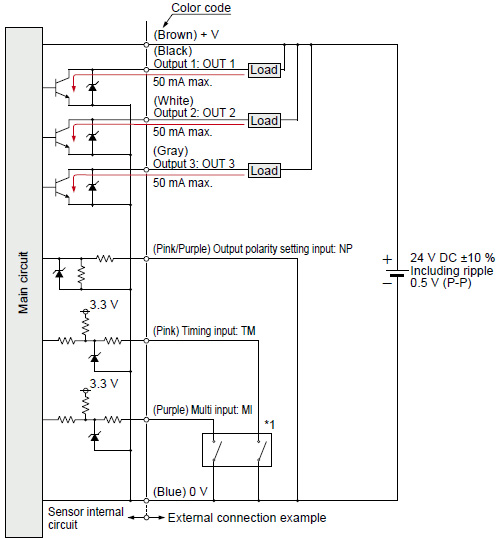
I/O circuit diagrams
| When selecting NPN output |
*1
| Non-voltage contact |
 |
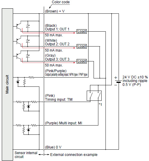
| When selecting PNP output |
*1
| Non-voltage contact or PNP open-collector transistor output |
 |
High [+5 V to +30 V DC (source current 0.04 mA or less)] : Effective
Low (0 to 0.6 V DC or open) : Ineffective |
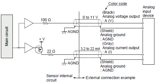
| Analog output (common in NPN output type and PNP output type) |
Notes:
| 1) |
Analog output is not equipped with the short-circuit protection. Do not short-circuit or apply voltage to them. |
| 2) |
Use shielded wires for analog outputs. |
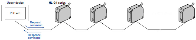
Communication specifications (High function type)
The HL-G1 can be connected to upper devices of RS-422/485.
When upper device sends the request command, the HL-G1 series send the response command.
| Communication method |
RS-422 |
RS-485 |
|
Full duplex |
Half duplex |
| Synchronization method |
Asynchronous communication method |
| Transmission code |
ASC ll |
| Baud rate |
9,600/19,200/38,400/115,200/230,400/460,800/921,600 bps |
| Data length |
8 bits |
| Stop bit length |
1 bit |
| Parity check |
None |
| BCC |
Yes |
| Termination code |
CR |
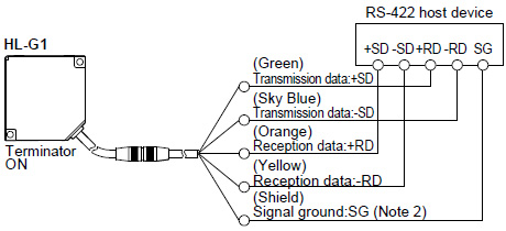
RS-422 1-to-1 connection
Notes:
| 1) |
The transmission data cable and reception data cable are both twisted-pair cables. |
| 2) |
The shield is connected to the 0 V side of the power supply line inside the sensor. |
| 3) |
Be sure to connect the signal ground. |
| 4) |
The sensor is of non-isolated type. Make sure that the potential difference between the sensor and RS-422 connecting device does not exceed 4V. A difference in potential in excess may cause the connecting device or the sensor to malfunction. |
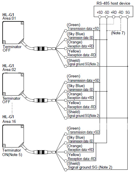
RS-485 1-to-N connection
- Connectable up to 16 units.
- Please set the prefix with no duplication.
Notes:
| 1) |
The transmission data cable and reception data cable are both twisted-pair cables. |
| 2) |
The shield is connected to the 0-V side of the power supply line inside the sensor. |
| 3) |
Be sure to connect the signal ground. |
| 4) |
The sensor is of non-isolated type. Make sure that the potential difference between the sensor and RS-485 connecting device does not exceed 4V. A difference in potential in excess may cause the connecting device or the sensor to malfunction. |
| 5) |
The sensor has a built-in terminating resistor. Be sure to turn ON the terminating resistor of the terminating sensor. |
| 6) |
Perform transition wiring for the transmission path. |
| 7) |
Connect the wires according to the specification of the equipment. |
Return to top
Return to top

 Business
> Industrial Devices
> Automation Controls Top
> FA Sensors & Components
> Measurement Sensors
> Measurement Sensors
> Compact Laser Displacement Sensor HL-G1
> I/O Circuit and Wiring diagrams
Business
> Industrial Devices
> Automation Controls Top
> FA Sensors & Components
> Measurement Sensors
> Measurement Sensors
> Compact Laser Displacement Sensor HL-G1
> I/O Circuit and Wiring diagrams