【Notification of Manufacturer Change for Panasonic Industrial Devices SUNX Products and Panasonic Industrial Devices SUNX Tatsuno Products】
From April 1, 2024, the terms "Panasonic Industrial Devices SUNX Co., Ltd." and "Panasonic Industrial Devices SUNX Tatsuno Co., Ltd."
in this page and in the manuals and other documents to be downloaded will all be replaced with "Panasonic Industry Co., Ltd." and applied accordingly.

 Business
> Industrial Devices
> Automation Controls Top
> FA Sensors & Components
> Measurement Sensors
> Measurement Sensors
> Ultra-compact Laser Collimated Beam Sensor HL-T1
> Cautions For Use
Business
> Industrial Devices
> Automation Controls Top
> FA Sensors & Components
> Measurement Sensors
> Measurement Sensors
> Ultra-compact Laser Collimated Beam Sensor HL-T1
> Cautions For Use
Ultra-compact Laser Collimated Beam Sensor HL-T1
|
Cautions For Use
| ・ | This website is a guide to select a suitable product. Be sure to read instruction manual attached to the product prior to its use. |
|---|
- Never use this product as a sensing device for personnel protection.
- In case of using sensing devices for personnel protection, use products which meet laws and standards, such as OSHA, ANSI or IEC etc., for personnel protection applicable in each region or country.
- Do not operate products using methods other than the ones described in the instruction manual included with each product. Control or adjustment through procedures other than the ones specified may cause hazardous laser radiation exposure.
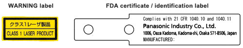
- This product is a class 1 laser product according to IEC/EN/JIS/GB and FDA regulations.
- Avoid observing beams in a dark surrounding environment.
- Do not look at beams using an optical device such as an optical telephoto system.
- Never attempt to disassemble, repair, or modify this product.
- The following label is affixed to this product. Handle the product according to the instruction given on the label.
(The English warning label based on FDA regulations is pasted on the FDA conformed type.)
Safety standards for laser beam products
- For the purpose of preventing any injury which may occur to the user by the use of the laser product in advance, the following standards have been established by the IEC Standards, EN Standards, JIS Standards, GB Standards and FDA Regulations.
| IEC | : IEC 60825-1:2014 | |
| EN | : EN 60825-1:2014/A11:2021 | |
| JIS | : JIS C 6802:2014 | |
| GB | : GB 7247.1-2012 | |
| FDA | : PART 1040.10, 1040.11 |
| Based on the above standards, the HL-T series are classified as Class 1 laser products. |
|---|
| Classification by IEC 60825-1 |
| Classification | Description |
|---|---|
| Class 1 | A laser that is safe when operated under operating conditions that can be reasonably foreseen. |
Note: When an unexpected failure occurs, dangerous radiation may be generated. Therefore, pay special attention to safety.
Safe use of laser products
- For the purpose of preventing users from suffering injuries by laser products, each standard stipulates (Safety of laser products). Kindly check the standards before use.
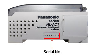
How to identify newer and older controllers
The controller for HL-T1 series, HL-AC1(P), has been upgraded from the shipment in July 1st, 2019.
- It can not be used new and previous controllers mixed when using with calculation unit, HL-AC1-CL.
- Some functions are different depending on the versions. Please refer to each new and previous manuals for functions in detail.
>>Go to "Manual download" page.
■How to distinguish the controllers
The serial No. on main unit and OS label will be changed as below.
|
| Before the upgrade (Software Ver.2/Ver.1) |
After the upgrade (Software Ver.3) |
|---|---|
| Serial No.:0******(It starts with 0.) | Serial No.:9******(It starts with 9.) |
Functions
| Function | Details | ||||
|---|---|---|---|---|---|
| Zero reset function | The following tasks can be done by executing zero reset.
|
||||
| Auto scaling function | The auto scaling function selects whether to display the laser beam reception amount in the main-digital display in “mm” units or in “%” units, and determines whether the amount of laser beam received or the amount of laser beam interrupted is displayed. With the set standard laser beam reception amount as the reference value, the current laser beam reception amount (laser beam interrupted amount) is scaled automatically and is displayed as well as being output. | ||||
| Standard received light setting | This function registers and stores the current laser beam reception amount in memory as the standard laser beam reception amount. The laser beam reception amount during full laser beam entry becomes the 100 % laser beam reception amount’s full scale (F.S.). If this function is used, the display and the linear output are set on the full scale (F.S.) automatically. It can also be used to correct the laser beam reception amount when there is a change in the laser beam reception amount due to dirt, etc. on the front glass. | ||||
| Scaling function | The scaling function is a function that changes the display value to the desired amount with respect to the setting value. At the desired distance, the display value can be input and changed. | ||||
| Hysteresis width setting function | This function sets the hysteresis to the desired value. | ||||
| Monitor focus function | With this function, the linear output range and inclination, etc. with respect to the display value can be specified. Setting is done by determining the 2 output values with respect to the desired display values. | ||||
| Differential function | This function makes the amount of change in the measured value an output value. Use this function when measuring if you are paying attention to changes in measured values, as when counting the number of workpieces, etc. | ||||
| Display reverse function | The digital display’s direction can be selected. The forward direction or the reverse direction to match the direction of installation on the equipment can be selected. | ||||
| ECO display function | This function makes the display dark and saves electric power. | ||||
| Display digits limitation function | This determines the number of display digits in the main-digital and sub-digital displays. If the number of digits is limited, the digits are turned off beginning with the lowest order digit. | ||||
| Zero reset memory function | This selects whether or not to save the zero reset level in memory when the power is turned OFF. If you desire to reproduce the zero reset level from the previous operating session when you turn the power ON again, then enable this function. If this function is enabled, the zero reset level data are written into the EEPROM each time. | ||||
| Key lock function | The controller’s key input can be disabled. Once the key input is disabled, the controller will not accept any key inputs until the key lock is released. Use this function to avoid changing the setting by mistake. |
Connection
- This product is made to satisfy the specifications when the sensor head is combined with the controller. In any other combination, not only may it not satisfy the specifications, but could be the cause of breakdown. So by all means, use it so that there is a combination of the sensor head and the controller.
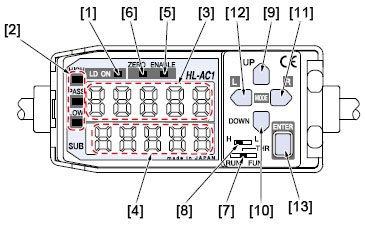
Functional description
|
| Description | Function | |||||||
|---|---|---|---|---|---|---|---|---|
| [1] | Laser emitting indicator (LD ON) (Green LED) |
Lights up when the sensor head is emitting laser beam. | ||||||
| [2] | Judgment output indicators (HIGH / PASS / LOW) (Orange / Green / Yellow LED) |
HIGH: Orange LED (lights up when measured value > HIGH threshold value) PASS: Green LED ( lights up when HIGH threshold value ≥ measured value ≥ LOW threshold value) LOW: Yellow LED (lights up when LOW threshold value > measured value) |
||||||
| [3] | Main digital display (5 digit red LED) |
When in the RUN mode, it displays the measured value (mm/%). During measurement hold, it displays the hold value (mm/%). In Reverse mode, the top and bottom are displayed in reverse. |
||||||
| [4] | Sub-digital display (5 digit yellow LED) |
When in the RUN mode, it displays the threshold value, voltage / current value, light reception amount or resolution. When in the THR mode, it displays the respective threshold values. In reverse mode, the top and bottom are displayed in reverse. | ||||||
| [5] | Enable indicator (ENABLE) (Green LED) |
Lights up when operation is normal. Goes off when operation is abnormal (if the sensor head is not connected when the power is turned on). | ||||||
| [6] | Zero reset indicator (ZERO) (Green LED) |
Lights up when the zero reset function is enabled. | ||||||
| [7] | Mode selection switch | The following 3 modes can be selected.
|
||||||
| [8] | Threshold value select switch | When in the THR / RUN mode, this switches the set threshold value (HIGH / LOW). | ||||||
| [9] | UP key |
|
||||||
| [10] | DOWN key |
|
||||||
| [11] | RIGHT key |
|
||||||
| [12] | LEFT key |
|
||||||
| [13] | ENT key |
|
Others
- This product outputs the judgment of the laser light analog quantity. Since there is variation in the light intensity between the center and the edges of the detection area, and the emitter side and the receiver side, the “display value” does not equal “the actual dimensions”, so caution is necessary.
Use the displayed dimensional value as a criterion. - If the object being measured has a mirror surface or is a transparent body, it may be impossible to measure it accurately, so please exercise caution.
- Absolutely do not attempt to disassemble this product.
- Do not use this product during the transient state when the power supply is turned ON.
BY EMAIL
- U.S.A.
- +1-800-344-2112
- Europe
- +49-89-45354-1000
- China
- +86-10-59255988
- Singapore
- +65-6299-9181


Requests to customers (Automation Control Components & Industrial Device) [Excluding specific product]
Requests to customers (Automation Control Components & Industrial Device) [For specific product]
Requests to customers (FA Sensors & Components [Excluding motors])
Requests to customers (Dedicated to industrial motors)
- COMPONENTS & DEVICES
- FA SENSORS & COMPONENTS
- Fiber Sensors
- Photoelectric Sensors / Laser Sensors
- Micro Photoelectric Sensors
- Light Curtains / Safety Components
- Area Sensors
- Inductive Proximity Sensors
- Particular Use Sensors
- Sensor Options
- Wire-Saving Systems
- Programmable Controllers / Interface Terminal
- Human Machine Interface
- Pressure Sensors / Flow Sensors
- Measurement Sensors
- Static Control Devices
- Laser Markers / 2D Code Readers
- Machine Vision System
- Energy Management Solutions
- Timers / Counters / FA Components
- MOTORS
![]()