【Notification of Manufacturer Change for Panasonic Industrial Devices SUNX Products and Panasonic Industrial Devices SUNX Tatsuno Products】
From April 1, 2024, the terms "Panasonic Industrial Devices SUNX Co., Ltd." and "Panasonic Industrial Devices SUNX Tatsuno Co., Ltd."
in this page and in the manuals and other documents to be downloaded will all be replaced with "Panasonic Industry Co., Ltd." and applied accordingly.

 Business
> Industrial Devices
> Automation Controls Top
> FA Sensors & Components
> Measurement Sensors
> Measurement Sensors
> LED Collimated Beam Sensor LA-300
> I/O Circuit and Wiring diagrams
Business
> Industrial Devices
> Automation Controls Top
> FA Sensors & Components
> Measurement Sensors
> Measurement Sensors
> LED Collimated Beam Sensor LA-300
> I/O Circuit and Wiring diagrams
LED Collimated Beam Sensor LA-300
|
Partly Order Discontinued
Partly Order Discontinued
|
|
I/O Circuit and Wiring diagrams
LA-A1
NPN output type
|
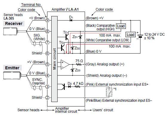
| Symbols・・・ | D1:Reverse supply polarity protection diode D2:Input protection diode ZD1, ZD2, ZD3 : Surge absorption zener diode Tr1, Tr2 : NPN output transistor |
|---|
| Non-voltage contact or NPN open-collector transistor |
 |
| External synchronization input (Voltage between ES+ and ES– ) Low: 0 to 1 V High: +V or open |
| Notes: 1) | When ES+ (pink) and ES– (pink/blue) of external synchronization input are connected, both HIGH and LOW comparative outputs are triggered in the mode selected by the external synchronization selection switch. If the external synchronization function is not used, always short-circuit ES+ and ES– and set the external synchronization selection switch to gate trigger. |
|---|---|
| 2) | To use the analog output (gray), choose a device with an input impedance of 1 MΩ, or more, and connect the shield wire of the analog output to 0 V (common input) of the device. |
| 3) | Insulate all unused wires individually to avoid miscontact. |
BY EMAIL
- U.S.A.
- +1-800-344-2112
- Europe
- +49-89-45354-1000
- China
- +86-10-59255988
- Singapore
- +65-6299-9181


Requests to customers (Automation Control Components & Industrial Device) [Excluding specific product]
Requests to customers (Automation Control Components & Industrial Device) [For specific product]
Requests to customers (FA Sensors & Components [Excluding motors])
Requests to customers (Dedicated to industrial motors)
- COMPONENTS & DEVICES
- FA SENSORS & COMPONENTS
- Fiber Sensors
- Photoelectric Sensors / Laser Sensors
- Micro Photoelectric Sensors
- Light Curtains / Safety Components
- Area Sensors
- Inductive Proximity Sensors
- Particular Use Sensors
- Sensor Options
- Wire-Saving Systems
- Programmable Controllers / Interface Terminal
- Human Machine Interface
- Pressure Sensors / Flow Sensors
- Measurement Sensors
- Static Control Devices
- Laser Markers / 2D Code Readers
- Machine Vision System
- Energy Management Solutions
- Timers / Counters / FA Components
- MOTORS
![]()