【Notification of Manufacturer Change for Panasonic Industrial Devices SUNX Products and Panasonic Industrial Devices SUNX Tatsuno Products】
From April 1, 2024, the terms "Panasonic Industrial Devices SUNX Co., Ltd." and "Panasonic Industrial Devices SUNX Tatsuno Co., Ltd."
in this page and in the manuals and other documents to be downloaded will all be replaced with "Panasonic Industry Co., Ltd." and applied accordingly.
Dual Display Digital Pressure Sensor [For Gas] DP-100L
I/O Circuit and Wiring diagrams
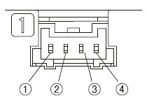
Terminal arrangement diagram of the connector on the sensor side
|
|
| Terminal No. |
Designation |
| ① |
+V |
| ② |
Communication output (C/Q) (Note) |
| ③ |
Control output (DO) |
| ④ |
0V |
|
| Note: |
When the sensor is used as an ordinary sensor, the communication output (C/Q) provides the same output operation as the control output (DO). |
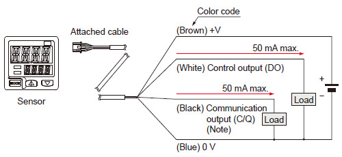
WIRING DIAGRAMS
DP-10□ZL3-M-P
Discrete wire type
<When using as an ordinary sensor> |
 |
|
<When connecting to the IO-Link master> |
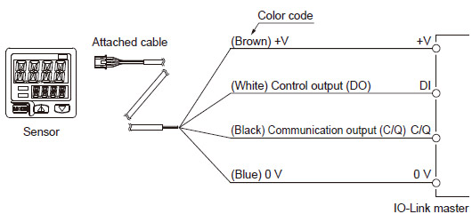 |
|
| Note: |
When the sensor is used as an ordinary sensor, the communication output (C/Q) provides the same output operation as the control output (DO). |
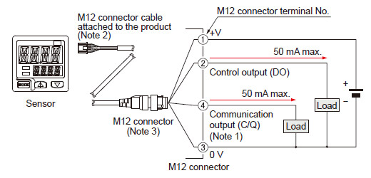
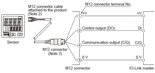
DP-10□ZL3-M-P-C
M12M12 connector type
<When using as an ordinary sensor> |
 |
|
<When connecting to the IO-Link master> |
 |
|
| Notes: 1) |
When the sensor is used as an ordinary sensor, the communication output (C/Q) provides the same output operation as the control output (DO). |
| 2) |
Be sure to use the dedicated M12 connector cable attached to the product. Note that the pin arrangement is different from that for commercially
available M12 connector cables. |
| 3) |
When wiring with the discrete wire or extending the cable from the dedicated M12 connector attached to the product, separately prepare commercially
available M12 connector cable. |
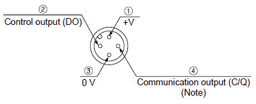
M12 connector terminal arrangement diagram
|
|
| Terminal No. |
Designation |
| ① |
+V |
| ② |
Control output (DO) |
| ③ |
0V |
| ④ |
Communication output (C/Q) (Note) |
|
| Note: |
When the sensor is used as an ordinary sensor, the communication output (C/Q) provides the same output operation as the control output (DO). |
Return to top
Return to top

 Business
> Industrial Devices
> Automation Controls Top
> FA Sensors & Components
> Pressure Sensors / Flow Sensors
> Pressure Sensors / Flow Sensors
> Dual Display Digital Pressure Sensor [For Gas] DP-100L
> I/O Circuit and Wiring diagrams
Business
> Industrial Devices
> Automation Controls Top
> FA Sensors & Components
> Pressure Sensors / Flow Sensors
> Pressure Sensors / Flow Sensors
> Dual Display Digital Pressure Sensor [For Gas] DP-100L
> I/O Circuit and Wiring diagrams